Ford Fiesta: Supplemental Restraint System / Front Impact Severity Sensor. Removal and Installation
Removal
 WARNING:
The following procedure prescribes critical repair steps
required for correct restraint system operation during a crash. Follow
all notes and steps carefully. Failure to follow step instructions may
result in incorrect operation of the restraint system and increases the
risk of serious personal injury or death in a crash.
WARNING:
The following procedure prescribes critical repair steps
required for correct restraint system operation during a crash. Follow
all notes and steps carefully. Failure to follow step instructions may
result in incorrect operation of the restraint system and increases the
risk of serious personal injury or death in a crash.
NOTE: Removal steps in this procedure may contain installation details.
-
Depower the SRS .
Refer to: Supplemental Restraint System (SRS) Depowering and Repowering (501-20B Supplemental Restraint System, General Procedures).
-
Remove the front bumper cover.
Refer to: Front Bumper Cover (501-19 Bumpers, Removal and Installation).
LH sensor
-
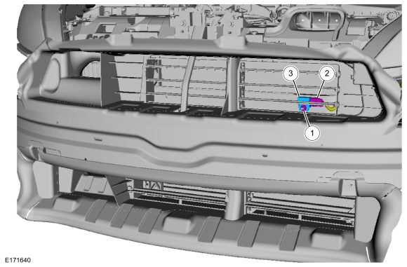
NOTE: With active grill shutter shown, without similar.
-
Remove the nut.
Torque: 93 lb.in (10.5 Nm)
-
Disconnect the electrical connector.
-
Remove the front impact severity sensor.
-
Remove the nut.
 |
RH sensor with active grill shutter
-
Position aside the RH side air deflector.
 |
RH sensor
-
NOTE: Active grill shutter panel is removed for clarity.
-
Remove the nut.
Torque: 93 lb.in (10.5 Nm)
-
Disconnect the electrical connector.
-
Remove the front impact severity sensor.
-
Remove the nut.
 |
Installation
-
NOTE: Make sure the front impact severity sensor mating surfaces are clean and free of foreign material.
To install, reverse the removal procedure.
-
Repower the SRS .
Refer to: Supplemental Restraint System (SRS) Depowering and Repowering (501-20B Supplemental Restraint System, General Procedures).
 Front Door Side Impact Sensor. Removal and Installation
Removal
WARNING:
The following procedure prescribes critical repair steps
required for correct restraint system operation during a crash...
 Driver Knee Airbag. Removal and Installation
Special Tool(s) /
General Equipment
Interior Trim Remover
Removal
WARNING:
The following procedure prescribes critical repair steps
required for correct restraint system operation during a crash...
Other information:
Ford Fiesta 2014 - 2019 Service Manual: Instrument Panel Passenger Side Finish Panel. Removal and Installation
Removal Release the retaining tabs and remove the glove compartment. Release the retaining tabs and remove the instrument panel passenger side finish panel. Disconnect the electrical connector...
Ford Fiesta 2014 - 2019 Service Manual: Exterior Lighting - Overview. Description and Operation
Headlamps The headlamp system consists of: Headlamp assemblies Headlamp switch LH multifunction switch BCM The halogen headlamp system is a quad-beam pattern system. It consists of replaceable low and high beam bulbs in each headlamp assembly...
Categories
- Manuals Home
- Ford Fiesta Service Manual (2014 - 2019)
- General Information
- Engine
- Engine System - General Information
- Engine Cooling - 1.6L EcoBoost (132kW/180PS) – Sigma
- Front Subframe. Removal and Installation
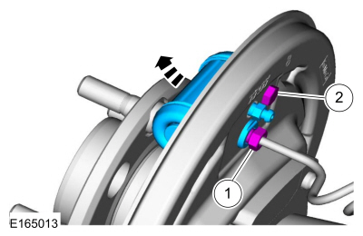
Brake Backing Plate. Removal and Installation
Removal
NOTE: Removal steps in this procedure may contain installation details.
Remove the brake shoes.Refer to: Brake Shoes (206-02 Drum Brake, Removal and Installation).
Disconnect the brake tube fitting.
Torque: 159 lb.in (18 Nm) Remove the bolt and wheel cylinder.
Torque: 106 lb.in (12 Nm)
 Disconnect the brake shoe lever fitting and re