Ford Fiesta: Supplemental Restraint System / Occupant Classification System (OCS) Sensor. Removal and Installation
Special Tool(s) / General Equipment
| Hog Ring Plier |
Removal
 WARNING:
The following procedure prescribes critical repair steps
required for correct restraint system operation during a crash. Follow
all notes and steps carefully. Failure to follow step instructions may
result in incorrect operation of the restraint system and increases the
risk of serious personal injury or death in a crash.
WARNING:
The following procedure prescribes critical repair steps
required for correct restraint system operation during a crash. Follow
all notes and steps carefully. Failure to follow step instructions may
result in incorrect operation of the restraint system and increases the
risk of serious personal injury or death in a crash.
NOTICE: To prevent system failure, carry out the OCS reset when a front passenger seat cushion is disassembled, a new trim cover is installed or an OCS service kit is installed. Use a scan tool to carry out the OCS reset command.
NOTICE: The cushion heater mat on a front outboard passenger seat is not serviced separately. If a new cushion heater mat is needed on the front passenger seat, install an OCS service kit equipped with a heater mat. Failure to follow this instruction may result in incorrect operation of the OCS .
NOTE: Removal steps in this procedure may contain installation details.
All seats
-
Remove the front seat.
Refer to: Front Seat (501-10 Seating, Removal and Installation).
-
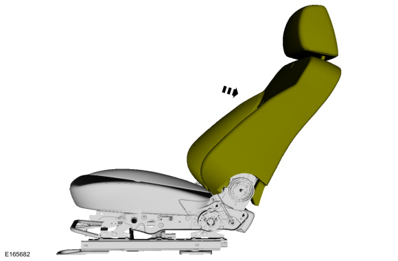
Recline the seat backrest.
 |
-
-
Remove the bolt cover.
-
Remove the bolt.
Torque: 35 lb.in (4.0 Nm)
-
Remove the recline handle.
-
Remove the bolt cover.
 |
-
-
If equipped.
Release the retainer and remove the height adjustment handle.
-
Remove the side shield screw.
Torque: 27 lb.in (3.0 Nm)
-
Push the side shield forward and remove the side shield.
-
If equipped.
 |
-
-
Remove the screw.
Torque: 27 lb.in (3 Nm)
-
Pull the recliner cover up then out.
-
Release the clip and remove the recliner cover.
-
Remove the screw.
 |
Heated seat
-
Disconnect the heated seat electrical connectors and position the wiring harness aside.
 |
All seats except Recaro™
-
Detach the backrest cover straps and position aside the backrest cover.
 |
Recaro™ seat
-
Detach the cushion cover J-clips and position the cushion cover aside.
 |
All seats
-
NOTE: Base seat shown, Recaro™ similar.
Release the seat cushion cover J-clips from the cushion frame.
 |
Recaro™ seats
-
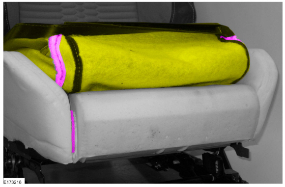
NOTICE: Use care when separating the cushion trim cover from the hook-and-loop strips, or the hook-and-loop strips can be torn from the cushion foam pad.
Release the hook-and-loop strips and position aside the cushion cover.
 |
-
NOTICE: Use care when separating the cushion trim cover from the hook-and-arrows or the hook can be torn from the cushion foam pad.
On both sides.
Release the hook-and-arrows.
 |
Seats equipped with original equipment (OE) occupant classification system (OCS)
-
Remove the cushion foam and cover as an assembly.
 |
All seats
-
-
Disconnect the OCS sensor electrical connector.
-
Release the tabs.
-
Remove the OCS sensor from the bracket.
-
Disconnect the OCS sensor electrical connector.
 |
-
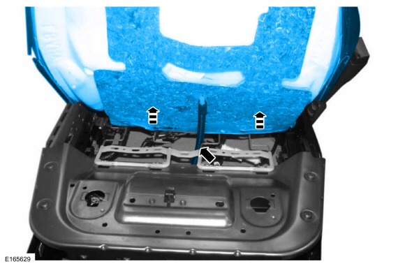
NOTE: Original equipment (OE) OCS shown, service kit similar.
Remove the pin-type retainers.
 |
-
NOTE: Follow the unique instructions or graphic for this step in installation
Route out the OCS hose and sensor from between the seat cushion support wires and remove the OCS .
 |
Recaro™ seats
-
NOTICE: Use care when separating the seat cushion trim cover from the hook-and-loop strips or the hook-and-loop strips may be torn from the seat cushion foam pad.
NOTICE: Use care when separating the cushion trim cover from the hook-and-arrow strip, or the hook can be torn from the cushion foam pad.
On both sides.
Release the hook-and-loop strips, the hook-and-arrows and remove the seat cushion cover.
 |
All seats except Recaro™
-
-
Invert the cushion cover sides.
-
Remove the hog rings.
-
Invert the front and rear of the cushion cover.
-
Remove the hog rings.
-
Invert the cushion cover sides.
 |
Installation
-
NOTICE: Inspect the OCS bladder, seat cushion pan and support assembly for any foreign objects before installing the OCS to the seat cushion pan. Remove any foreign objects. Failure to follow these instructions may result in incorrect operation of the OCS and may cause system failure.
To install, reverse the removal procedure.
Use the General Equipment: Hog Ring Plier
-
During installation, make sure the OCS hose is routed correctly and not
kinked or trapped on top of the seat cushion wire supports.
 |
-
Install the passenger seat. Do not prove out the SRS at this time.
Refer to: Front Seat (501-10 Seating, Removal and Installation).
-
WARNING:
Occupant Classification System (OCS) parts are
calibrated as an assembly and must only be replaced in the configuration
they are sold. Never separate parts of an assembly. Failure to follow
this instruction may result in incorrect operation of the OCS and
increases the risk of serious personal injury or death in a crash.
WARNING:
Make sure the front passenger seat repair is
complete, the seat and all attached components (head restraint, seat
side shield, etc.) are correctly assembled, and the seat is correctly
installed to the vehicle before using System Reset to rezero the seat
weight. Failure to follow these instructions may result in incorrect
operation of the occupant classification system (OCS) and increases the
risk of serious personal injury or death in a crash.
NOTICE: To prevent system failure, take the following precautions before carrying out the OCS reset.
- Make sure the voltage to the OCSM is greater than 8 volts and less than 18 volts.
- Make sure the OCS is not below 42.8 °F ( 6 °C) or above 96.7 °F ( 36 °C) when initiating the OCS reset process. If the vehicle has been exposed to extreme cold or hot temperatures, the vehicle must be exposed and kept at a temperature between 42.8 °F ( 6 °C) to 96.7 °F ( 36 °C) for a minimum of 30 minutes.
- Make sure nothing is present on the passenger seat before and during the OCS reset process.
- Prior to carrying out the OCS reset, make sure a minimum of 8 seconds has elapsed after cycling the ignition switch on.
-
If the first system reset attempt was successful, proceed to prove out the SRS .
-
If the first system reset attempt was not successful, carry out a thorough visual inspection of the OCS
connector and wiring for damage, pressure sensor hose for kinks and or
damage, and seat-related wiring harness and body wiring harness
terminals and connectors for damage. Repair any concerns found and
proceed to the next step.
-
Carry out a second OCS reset. Cycle the ignition switch after the OCS
reset. If the second attempt is unsuccessful, install a new OCS service
kit.
-
Prove out the SRS
by turning the ignition from ON to OFF. Wait 10 seconds, then turn the
ignition back to ON and monitor the airbag warning indicator with the
airbags installed. The airbag warning indicator illuminates continuously
for approximately 6 seconds and then turns off. If a SRS fault is
present, the airbag warning indicator will fail to light, remain lit
continuously, or flash.
-
The flashing might not occur until approximately 30
seconds after the ignition has been turned from OFF to ON. This is the
time required for the RCM to complete the testing of the SRS . If the airbag warning indicator is inoperative and a SRS
fault exists, a chime sounds in a pattern of 5 sets of 5 beeps. If
this occurs, diagnose and repair the airbag warning indicator and any SRS faults.
-
Clear all continuous Diagnostic Trouble Codes (DTCs) from the RCM and OCSM using a diagnostic scan tool.
 Driver Knee Airbag. Removal and Installation
Special Tool(s) /
General Equipment
Interior Trim Remover
Removal
WARNING:
The following procedure prescribes critical repair steps
required for correct restraint system operation during a crash...
 Passenger Airbag. Removal and Installation
Removal
WARNING:
The following procedure prescribes critical repair steps
required for correct restraint system operation during a crash...
Other information:
Ford Fiesta 2014 - 2019 Service Manual: Camshaft Position (CMP) Sensor LH. Removal and Installation
Removal NOTE: Removal steps in this procedure may contain installation details. Remove the engine appearance cover. Disconnect the CMP sensor electrical connector, remove the retainer and the CMP sensor...
Ford Fiesta 2014 - 2019 Service Manual: Parking Brake. Diagnosis and Testing
Symptom Chart(s) Symptom Chart: Parking Brake and Actuation Diagnostics in this manual assume a certain skill level and knowledge of Ford-specific diagnostic practices. REFER to: Diagnostic Methods (100-00 General Information, Description and Operation)...
Categories
- Manuals Home
- Ford Fiesta Service Manual (2014 - 2019)
- Front Subframe. Removal and Installation
- Manual Transmission - 6-Speed Manual Transmission – B6
- Valve Clearance Adjustment. General Procedures
- Timing Belt. Removal and Installation
- Clutch - 6-Speed Manual Transmission – B6
Ride Height Measurement. General Procedures
Special Tool(s) / General Equipment
Surface GaugeCheck
Ride Height Measurement - Front
NOTE: Make sure that the vehicle is positioned on a flat, level surface and the tires are inflated to the correct pressure. Vehicle should have a full tank of fuel.
Ride height = 2-3Measurement 2
Measurement 3
Use the General Equipment: Surface Gauge