Ford Fiesta: Clutch - 6-Speed Manual Transmission – B6 / Clutch - Overview. Description and Operation
Clutch Components
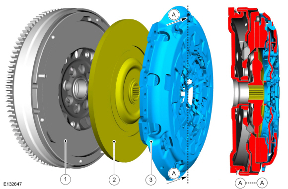
| Item | Part Number | Description |
| 1 | 6375B | Flywheel |
| 2 | part of 7L596 | Clutch disc |
| 3 | part of 7L596 | Cover assembly |
| A | — | Sectional plane A |
The clutch consists of:
- Flywheel
- Clutch disc
- Cover assembly
The clutch transmits the engine torque to the transmission.
The clutch is a single plate, dry friction disc with a diaphragm spring clutch pressure plate. The clutch disc has a hub splined to the transmission input shaft. The clutch disc has friction material where it contacts the flywheel and the clutch pressure plate. The clutch pressure plate applies pressure to the clutch disc, holding it tightly against the surface of the flywheel. In the engaged position, the diaphragm spring holds the clutch pressure plate against the clutch disc so that engine torque is transmitted to the input shaft.
When the clutch pedal is applied, the release bearing pushes the diaphragm spring center of the clutch pressure plate toward the flywheel. The diaphragm spring pivots at the fulcrum, relieving the load on the clutch pressure plate. The clutch slave cylinder assists in the effort it takes to relieve the load on the clutch pressure plate. Steel spring straps riveted to the clutch pressure plate cover pull the clutch pressure plate from the clutch disc, disengaging the engine torque from the transmission.
Clutch Disc
The clutch disc has a splined hub (with integral torsional dampening springs) which attaches the clutch disc to the input shaft. Engine output is coupled to the input shaft by the friction existing between the clutch disc facings and the flywheel/clutch pressure plate assembly.
Clutch Cover Assembly
The clutch pressure plate applies pressure to the clutch disc holding it tightly against the surface of the flywheel. In the engaged position, the diaphragm spring holds the clutch pressure plate against the clutch disc so that engine torque is transmitted to the input shaft.
Clutch Release Hub and Bearing
The clutch system is disengaged when the clutch pedal is pressed and engaged when the clutch pedal is released. When the clutch pedal is pressed, it pushes the clutch master cylinder plunger, which transmits hydraulic pressure to the clutch slave cylinder. The slave cylinder engages and compresses through the release bearing and the clutch pressure plate diaphragm spring, releasing the pressure on the clutch disc. This displacement removes the spring load from the clutch pressure plate and eliminates the coupling friction between the engine and the transmission.
Self-adjusting Clutches
The clutch size has increased with the introduction of more powerful engines. The self-adjusting clutch eliminates the increase in operating force which occurs as wear increases.
The advantages of the self-adjusting clutch are as follows:
- Constant operating force throughout the whole service life of the clutch.
- Increased service life of the clutch friction disc.
- Shorter release bearing travel.
Self-adjusting clutches cannot be reset after the clutch disc has been removed and must also be replaced.

 Clutch - System Operation and Component Description. Description and Operation
System Operation
How the clutch works
Cross-sectional view of a single disc dry clutch
Item
Description
A
Clutch disengaged
B
Clutch engaged
1
Flywheel
2
Clutch disc
3
Pressure plate
4
Diaphragm spring
5
Transmission input shaft
6
Clutch cover
7
Crankshaft
The..
Other information:
Ford Fiesta 2014 - 2019 Service Manual: Seat Position Sensor. Removal and Installation
Removal NOTE: Removal steps in this procedure may contain installation details. WARNING: Turn the ignition OFF and wait one minute to deplete the backup power supply. Ignition must remain OFF until repair is complete. Failure to follow this instruction may result in serious personal injury or death in the event of an accidental deployment. Turn the ignitio..
Ford Fiesta 2014 - 2019 Service Manual: Wheels and Tires. Diagnosis and Testing
Preliminary Inspection Verify the customer concern by carrying out a road test on a smooth road. If any vibrations are apparent, Refer to the Symptom Chart: NVH. To maximize tire performance, inspect for signs of incorrect inflation and uneven wear, which may indicate a need for balancing, rotation or front suspension alignment. Correct tire pressure and d..
Categories
- Manuals Home
- Ford Fiesta Service Manual (2014 - 2019)
- Valve Cover. Removal and Installation
- Manual Transmission, Clutch, Transfer Case and Power Transfer Unit
- Cylinder Head. Removal and Installation
- Engine Cooling - 1.6L EcoBoost (132kW/180PS) – Sigma
- Engine System - General Information
Ride Height Measurement. General Procedures
Special Tool(s) / General Equipment
Surface GaugeCheck
Ride Height Measurement - Front
NOTE: Make sure that the vehicle is positioned on a flat, level surface and the tires are inflated to the correct pressure. Vehicle should have a full tank of fuel.
Ride height = 2-3Measurement 2
Measurement 3
Use the General Equipment: Surface Gauge