Ford Fiesta: Clutch Controls - 5-Speed Manual Transmission – B5/IB5/6-Speed Manual Transmission – B6 / Clutch Controls - System Operation and Component Description. Description and Operation
System Operation
Hydraulic Clutch Actuation System
The design of the clutch actuation system is very similar to that of a hydraulic brake system.
The hydraulic clutch actuation system uses a hydraulic line rather than a mechanical connection to transmit the pedal movement. The forces are transmitted purely hydraulically and the brake fluid is used for drive transmission.
A clutch master cylinder actuates a clutch slave cylinder through a hydraulic line. When the operating force is released, the hydraulic clutch actuation system is depressurized and the clutch slave cylinder is pushed back by the diaphragm spring of the clutch mechanism. With this type of actuation, the clutch release bearing remains in constant contact with the surrounding diaphragm spring of the clutch mechanism. The clutch release bearing must therefore be at a permanently speed-resistant.
The hydraulic clutch actuation system is supplied by the brake fluid reservoir.
Displaced hydraulic fluid can escape from the clutch master cylinder's compensating bore into the reservoir provided for this purpose. This means that the hydraulic clutch actuation system is self-adjusting.
The CPP sensor is located on the clutch master cylinder and is not adjustable. An actuated clutch pedal activates the CPP sensor.
The hydraulic clutch actuation system consists of the following components:
- Brake fluid reservoir
- Clutch pedal
- CPP sensor
- Clutch master cylinder
- Clutch slave cylinder
- Clutch hydraulic tubes
- Clutch release bearing
- Clutch pressure plate
- Clutch disc
Component Description
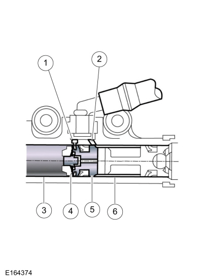
Clutch Master Cylinder
| Item | Description |
|---|---|
| 1 | Breather hole |
| 2 | Replenishing hole |
| 3 | Depressurized space |
| 4 | Pistons |
| 5 | Replenishing valve |
| 6 | Pressure chamber |
Function
The master cylinder is responsible for generating the fluid pressure for the hydraulic system.
When the piston is in the rest position, the volume in the pressure chamber and the reservoir is equalized via the compensating bore. When the piston moves over the compensating bore, fluid pressure builds up in the pressure chamber.
Operation
The hydraulic fluid is extracted from the brake fluid reservoir. This line ends in the clutch master cylinder. Due to the different piston diameters, a gear ratio can be set that reduces the pedal forces, e.g. when the diameter of the clutch master cylinder is smaller.
Clutch release bearings must withstand large axial forces. Previously, during normal driving, low play brought the vehicle to a stop when the clutch pedal was not actuated. The release bearing only rotated during engagement of a gear. Due to better protection against wear, current clutch release bearings always rotate. With hydraulic clutch actuation, the clutch slave cylinder can be integrated centrally in the clutch release bearing.
NOTICE: Long actuation of the clutch, e.g. at a red traffic light, creates an unnecessary load on the clutch release bearing, the clutch disc and the axial bearing of the crankshaft.
Clutch Slave Cylinder

| Item | Description |
|---|---|
| A | Sectional plane A |
| 1 | Connection – pressure line with hydraulic duct to the pressure chamber |
| 2 | Oil seal |
| 3 | Sleeve |
| 4 | Pressure chamber |
| 5 | Packing |
| 6 | Gaiter |
| 7 | Pressure spring |
| 8 | Pistons |
| 9 | Clutch release bearing |
Function
The task of the clutch slave cylinder is to transmit the fluid pressure generated in the clutch master cylinder as a force for actuating the clutch release bearing.
Operation
In the clutch slave cylinder, the pressure moves the piston in the axial direction. In the process, the clutch release bearing presses against the diaphragm spring of the pressure plate and interrupts the frictional connection between the clutch disc and the flywheel.
The diaphragm spring causes the clutch release bearing to be preloaded when not actuated.
 Clutch Controls - Overview. Description and Operation
Overall System and Components for Hydraulic Clutch Actuation
The
clutch provides a mechanical, positive engagement between two rotating
components...
 Clutch Controls. Description and Operation
Item
Part Number
Description
1
21402140
Brake fluid master cylinder
2
2K4782K478
Brake fluid filling reservoir
3
7A5437A543
Clutch master cylinder
4
75197519
Clutch pedal
5
7K5027K502
Clutch reservoir hydraulic tube
6
7A5647A564
Clutch slave cylinder
7
7A5127A..
Other information:
Ford Fiesta 2014 - 2019 Service Manual: Glass, Frames and Mechanisms - Vehicles With: One-Touch Open and Close Driver Window. Diagnosis and Testing
DTC Chart: Body Control Module (BCM) Diagnostics in this manual assume a certain skill level and knowledge of Ford-specific diagnostic practices. REFER to: Diagnostic Methods (100-00 General Information, Description and Operation). Body Control Module (BCM) DTC Chart DTC Description Action B1013:23 ..
Ford Fiesta 2014 - 2019 Service Manual: Clutch Pedal Position (CPP) Switch. Removal and Installation
Removal Top of travel switch Disconnect the electrical connector and remove CPP switch from the bracket. Bottom of travel switch Disconnect the electrical connector and remove CPP switch from the bracket. Installation To install, reverse the removal procedur..
Categories
- Manuals Home
- Ford Fiesta Service Manual (2014 - 2019)
- Valve Cover. Removal and Installation
- Engine - 1.6L EcoBoost (132kW/180PS) – Sigma
- Camshafts. Removal and Installation
- Engine. Assembly
- Service Information
Brake Drum. Removal and Installation
Removal
NOTE: Removal steps in this procedure may contain installation details.
 WARNING:
Before beginning any service procedure in this
manual, refer to health and safety warnings in section 100-00 General
Information. Failure to follow this instruction may result in serious
personal injury.
WARNING:
Before beginning any service procedure in this
manual, refer to health and safety warnings in section 100-00 General
Information. Failure to follow this instruction may result in serious
personal injury.
Remove the wheel and tire.
Refer to: Wheel and Tire (204-04A Wheels and Tires, Removal and Installation).