Ford Fiesta: Clutch Controls - 5-Speed Manual Transmission – B5/IB5/6-Speed Manual Transmission – B6 / Clutch Controls - Overview. Description and Operation
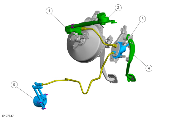
Overall System and Components for Hydraulic Clutch Actuation
The clutch provides a mechanical, positive engagement between two rotating components. The clutch can be engaged/released by mechanical, electrical or hydraulic components.
To disengage the clutch, the force exerted by the driver's foot is transmitted via the clutch pedal and a connecting rod to the piston of the clutch master cylinder.
Operating principle of hydraulic clutch actuation

| Item | Description |
|---|---|
| 1 | Brake fluid reservoir |
| 2 | Brake fluid filling reservoir |
| 3 | Clutch master cylinder |
| 4 | Clutch pedal |
| 5 | Clutch slave cylinder |
The clutch control system is a hydraulic/mechanical clutch system. The clutch control system disengages the clutch when the clutch pedal is pressed and engages the clutch when the clutch pedal is released. When the clutch pedal is pressed, pressure builds up in the clutch master cylinder and the release bearing in the clutch slave cylinder is actuated.
Advantages of a hydraulic clutch system:
- The clutch hydraulic tubes can be installed in the vehicle so they are protected.
- The hydraulic clutch permits transmission of force even when there is a considerable distance between the pedal and clutch.
- The hydraulic system requires no maintenance, only the brake fluid has to be changed according to the maintenance schedule.
- Fewer vibrations from the engine and transmission are transmitted to the clutch pedal.
Brake Fluid Reservoir
The brake fluid reservoir supplies brake fluid to the hydraulic clutch system and the brake system. The hydraulic clutch system and brake system are arranged separately inside the brake fluid reservoir. If a leak occurs in the hydraulic clutch system, the brake system continues to operate unrestricted.
Brake Fluid Filling Reservoir
The brake fluid filling reservoir is remotely attached to the brake fluid reservoir. Due to the brake fluid reservoirs location the brake fluid filling reservoir location allows the technician to easily fill the brake fluid reservoir.
Clutch Pedal
When the clutch pedal is pressed, the clutch master cylinder transmits hydraulic fluid pressure to the clutch slave cylinder. The clutch slave cylinder and the clutch release fork transfer the clutch pedal motion to the clutch release bearing. The release bearing presses against the pressure plate diaphragm spring, releasing the clutch disc. Once the clutch pedal is released, the diaphragm spring pushes the piston in the clutch slave cylinder back to its initial position. The non-positive connection between the clutch disc and the flywheel is re-established.
Clutch Master Cylinder
The clutch master cylinder generates the system pressure required to actuate the clutch. When the clutch pedal is pressed, the piston rod moves the clutch master cylinder piston. The hydraulic fluid in the clutch master cylinder is forced through the high-pressure tube to the clutch slave cylinder
Clutch Slave Cylinder
The central clutch slave cylinder is equipped with a release bearing and is attached to the clutch bell housing with three bolts. The release bearing is an interference installed in the clutch slave cylinder and is not serviced separately.
The hydraulic fluid forced from the piston in the clutch master cylinder moves the piston in the clutch slave cylinder which moves the release bearing in an axial direction. The release bearing inner ring presses onto the diaphragm spring. The non-positive connection between the clutch disc and the flywheel is interrupted.
 Clutch Controls - System Operation and Component Description. Description and Operation
System Operation
Hydraulic Clutch Actuation System
The design of the clutch actuation system is very similar to that of a hydraulic brake system...
Other information:
Ford Fiesta 2014 - 2019 Service Manual: Brake Pads. Removal and Installation
Special Tool(s) / General Equipment Brake Caliper Piston Retractor Materials Name Specification Motorcraft® DOT 4 LV High Performance Motor Vehicle Brake FluidPM-20 WSS-M6C65-A2 Removal NOTE: Removal steps in this procedure may contain installation details...
Ford Fiesta 2014 - 2019 Service Manual: Specifications
General Specifications Item Specification Generator - 1.0L EcoBoost engine Generator pulley ratio 2.62:1 Rating 97 amps at 750 rpm (min) to 166 amps at 2,300 rpm (max) Voltage regulator type Electronic internal with generator Generator..
Categories
- Manuals Home
- Ford Fiesta Service Manual (2014 - 2019)
- Clutch - 6-Speed Manual Transmission – B6
- Timing Belt. Removal and Installation
- Engine. Assembly
- Camshafts. Removal and Installation
- Valve Clearance Adjustment. General Procedures
Rear Wheel Speed Sensor. Removal and Installation
Removal
NOTE: Removal steps in this procedure may contain installation details.
Remove the retainer and pull the rear splash shield outward. Disconnect the electrical connector and detach the wiring retainer.

