Ford Fiesta: Exhaust System - 1.6L EcoBoost (132kW/180PS) – Sigma / Catalytic Converter. Removal and Installation
Special Tool(s) / General Equipment
| Cable Ties |
Removal
NOTE: Exhaust fasteners are of a torque prevailing design. Use only new fasteners with the same part number as the original. Torque values must be used as specified during reassembly to make sure of correct retention of exhaust components.
NOTE: Removal steps in this procedure may contain installation details.
-
With the vehicle in NEUTRAL, position it on a hoist.
Refer to: Jacking and Lifting - Overview (100-02 Jacking and Lifting, Description and Operation).
-
Remove the battery tray.
Refer to: Battery Tray - 1.6L EcoBoost (132kW/180PS) – Sigma (414-01 Battery, Mounting and Cables, Removal and Installation).
-
Remove the engine appearance cover.
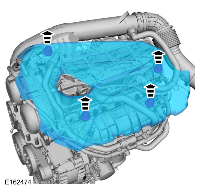 |
-
Detach the wiring harness retainer, then disconnect the HO2S and catalyst monitor sensor electrical connectors.
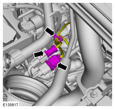 |
-
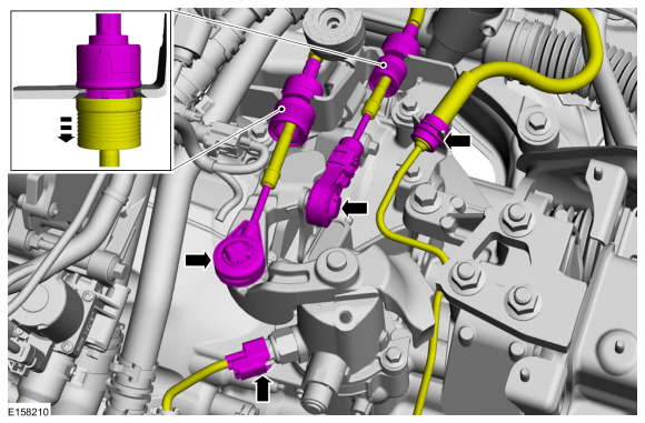
NOTICE: Gearshift cables must not be kinked or bent.
-
Disconnect the selector lever cable. Detach the
selector lever cables from the selector lever cable brackets.
-
Disconnect the electrical connector.
-
Disconnect the selector lever cable. Detach the
selector lever cables from the selector lever cable brackets.
 |
-
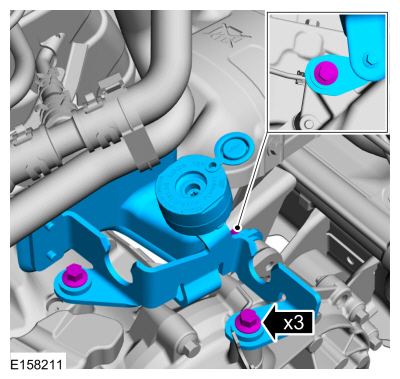
Remove the bolts and the bracket.
Torque: 18 lb.ft (25 Nm)
 |
-
Remove the HO2S .
Refer to: Heated Oxygen Sensor (HO2S) (303-14B Electronic Engine Controls - 1.6L EcoBoost (132kW/180PS) – Sigma, Removal and Installation).
-
Remove the CMS (catalyst monitor sensor).
Refer to: Catalyst Monitor Sensor (303-14B Electronic Engine Controls - 1.6L EcoBoost (132kW/180PS) – Sigma, Removal and Installation).
-
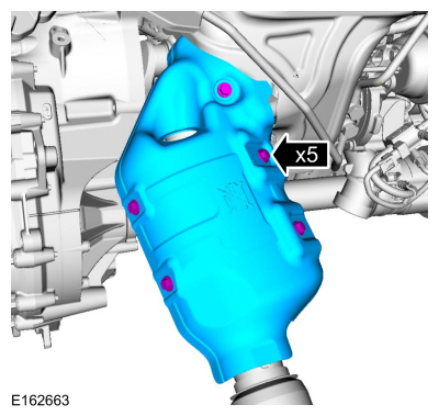
Remove the bolts and the heat shield.
Torque: 89 lb.in (10 Nm)
 |
-
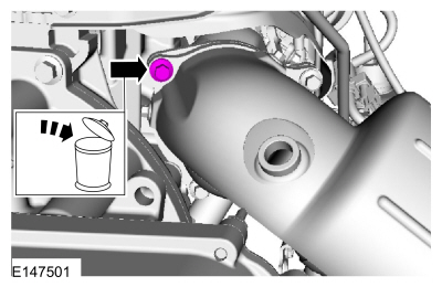
Remove and discard the catalytic converter bolt.
 |
-
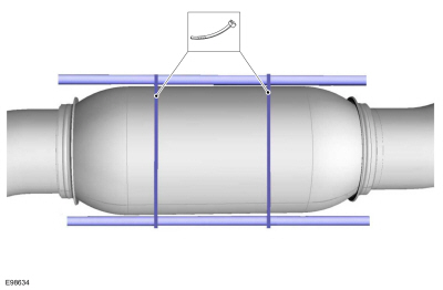
NOTICE: Do not excessively bend or twist the exhaust flexible pipe. Failure to follow these instructions may cause damage to the flexible pipe.
Support the exhaust flexible pipe with a support wrap or suitable splint.
Use the General Equipment: Cable Ties
 |
-
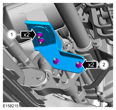
Remove the nuts and the catalytic converter mounting bracket.
Torque: 18 lb.ft (25 Nm)
 |
-
Detach the exhaust system isolator and position the exhaust system aside.
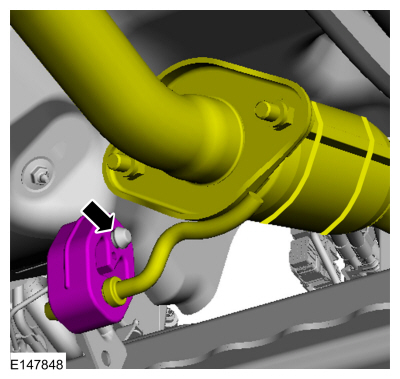 |
-
-
Remove and discard the nuts.
Torque: 35 lb.ft (48 Nm)
-
Remove and discard the gasket.
-
Position the exhaust system aside.
-
Remove and discard the nuts.
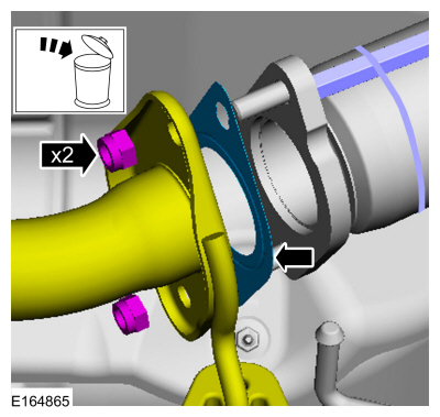 |
-
Remove and discard the catalytic convertor bolts.
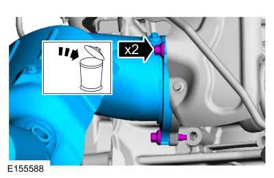 |
-
-
Position the catalytic converter upward.
-
Remove the catalytic convertor.
-
Position the catalytic converter upward.
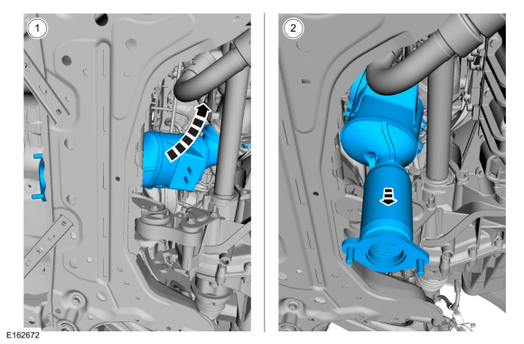 |
-
Remove and discard the catalytic converter to TC gasket.
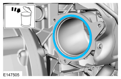 |
Installation
-
To install, reverse the removal procedure.
-
Install a new gasket and loosely install the 2 bolts.
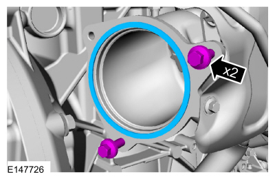 |
-
NOTICE: Failure to tighten the catalytic converter manifold fasteners in this sequence will cause the converter to develop an exhaust leak.
NOTE: Tighten the catalytic converter bolts in this sequence.
-
Position the catalytic converter on the 2 bolts and install the upper bolt.
Torque: 18 lb.ft (25 Nm)
-
Tighten the RH catalytic converter bolt.
Torque: 18 lb.ft (25 Nm)
-
Tighten the LH catalytic converter bolt.
Torque: 18 lb.ft (25 Nm)
-
Position the catalytic converter on the 2 bolts and install the upper bolt.
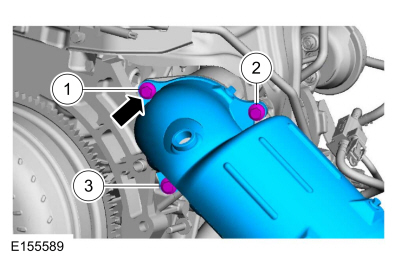 |
 Exhaust System. Diagnosis and Testing
Principles of Operation
Symptom Chart(s)
Symptom Chart: Symptom Chart - Exhaust System
Verify
the customer concern. Inspect the components of the exhaust system for
obvious signs of damage or other mechanical concerns using the following
chart...
 Muffler and Tailpipe. Removal and Installation
Special Tool(s) /
General Equipment
Air Body Saw
Removal
NOTICE:
The production muffler and tailpipe assembly is one-piece
construction...
Other information:
Ford Fiesta 2014 - 2019 Service Manual: Audio Front Control Module (ACM). Removal and Installation
Removal NOTE: Removal steps in this procedure may contain installation details. NOTE: This step is only necessary when installing a new component. NOTE: The PMI process must begin with the current ACM installed. If the current ACM does not respond to the daignostic scan tool, the tool may propmt for As-Built Data as part of the repair...
Ford Fiesta 2014 - 2019 Service Manual: Receiver Drier - 1.6L EcoBoost (132kW/180PS) – Sigma. Removal and Installation
Removal NOTE: Removal steps in this procedure may contain installation details. Recover the refrigerant. Refer to: Air Conditioning (A/C) System Recovery, Evacuation and Charging (412-00 Climate Control System - General Information) ...
Categories
- Manuals Home
- Ford Fiesta Service Manual (2014 - 2019)
- Valve Clearance Adjustment. General Procedures
- Maintenance Schedules
- Engine. Assembly
- Maintenance Schedules - Gasoline Engines. Description and Operation
- Clutch - 6-Speed Manual Transmission – B6
Ride Height Measurement. General Procedures
Special Tool(s) / General Equipment
Surface GaugeCheck
Ride Height Measurement - Front
NOTE: Make sure that the vehicle is positioned on a flat, level surface and the tires are inflated to the correct pressure. Vehicle should have a full tank of fuel.
Ride height = 2-3Measurement 2
Measurement 3
Use the General Equipment: Surface Gauge
