Ford Fiesta: Auxiliary Climate Control / Auxiliary Climate Control - System Operation and Component Description. Description and Operation
System Operation
Electric Booster Heater

| Item | Description |
|---|---|
| 1 | HS-CAN |
| 2 | Ambient Air Temperature (AAT) sensor |
| 3 | Electric booster heater |
| 4 | HVAC control module |
| 5 | Electric booster heater relay 1 |
| 6 | Electric booster heater relay 2 |
| 7 | IPC |
| 8 | PCM |
| 9 | ECT sensor |
The electric booster heater ensures that the passenger compartment can be quickly warmed up when ambient temperatures are low. It is a heater element made up of ceramic resistors that is mounted in the heater core and evaporator core housing. It directly heats the airflow into the passenger compartment rapidly in the case of low ambient temperatures.
The current is switched via two relays located in the auxiliary relay box. The electric booster heater power is supplied via a plug-in connection, the ground connection is screwed in.
The electric booster heater only operates while the engine is running and the HVAC temperature control knob is set to full warm. Its usage is controlled by the IPC .
The IPC energizes the electric booster heater relay(s) depending on the following parameters:
- Engine is running
- Engine coolant temperature is below 60 °C (140°F)
- Ambient air temperature is below 10 °C (50°F)
- Sufficient generator capacity is available
- The HVAC temperature control knob is set to full warm.
The electric booster heater has three stages. Only the first stage of the booster heater is switched on at ambient temperatures between 10 °C (50°F) and 20 °C (68°F) and an engine coolant temperature below 70 °C (158°F). All three stages of the booster heater are switched on at ambient temperatures below 10 °C (50°F) and an engine coolant temperature below 70 °C (158°F).
The electric booster heater is switched off when an engine coolant temperature of 70°C (158°F) or an ambient air temperature of 20°C (68°F) is exceeded.
 Auxiliary Climate Control - Overview. Description and Operation
Overview
The
electric booster heater is a heater element made up of ceramic
resistors that is mounted in the heater core and evaporator core
housing...
 Auxiliary Climate Control. Diagnosis and Testing
DTC Chart: Heating, Ventilation And Air Conditioning (HVAC) Control Module
Diagnostics
in this manual assume a certain skill level and knowledge of
Ford-specific diagnostic practices...
Other information:
Ford Fiesta 2014 - 2019 Service Manual: Rear Quarter Window Glass - 4-Door. Removal and Installation
Special Tool(s) / General Equipment 300-AST1770EDeluxe Air Knife AST405 Materials Name Specification Sika® SikaTack® MACH 60 / Sika® SikaTack® MACH 30 / Dow® BETASEAL™ Express - Sika Tack ASAP Urethane Adhesive - Dow Urethane One Step Glass PrimerBetaprime™ 5500/5500A/5500SA - Sika Ureth..
Ford Fiesta 2014 - 2019 Service Manual: Front Drive Halfshafts. Diagnosis and Testing
Inspection and Verification Verify the customer concern. Visually inspect for obvious signs of mechanical or electrical damage. If an obvious cause for an observed or reported concern is found, correct the cause (if possible) before proceeding to the next step If the cause is not visually evident, verify the symptom and refer to the Symptom Chart...
Categories
- Manuals Home
- Ford Fiesta Service Manual (2014 - 2019)
- Engine Cooling - 1.6L EcoBoost (132kW/180PS) – Sigma
- Clutch - 6-Speed Manual Transmission – B6
- Engine System - General Information
- Timing Belt. Removal and Installation
- Engine. Assembly
Brake Backing Plate. Removal and Installation
Removal
NOTE: Removal steps in this procedure may contain installation details.
Remove the brake shoes.Refer to: Brake Shoes (206-02 Drum Brake, Removal and Installation).
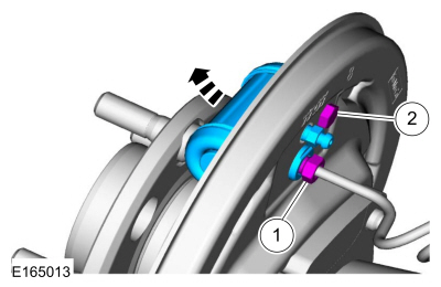
Disconnect the brake tube fitting.
Torque: 159 lb.in (18 Nm) Remove the bolt and wheel cylinder.
Torque: 106 lb.in (12 Nm)
 Disconnect the brake shoe lever fitting and re

