Ford Fiesta: Steering Column / Steering Wheel. Removal and Installation
Ford Fiesta 2014 - 2019 Service Manual / Steering System / Steering Column / Steering Wheel. Removal and Installation
Special Tool(s) / General Equipment
| Adhesive Tape |
Removal
NOTE: The removal steps in this procedure may include installation details.
-
Remove the driver airbag.
Refer to: Driver Airbag (501-20B Supplemental Restraint System, Removal and Installation).
-
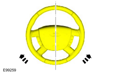
NOTE: Make sure that the road wheels are in the straight ahead position.
Position the road wheels in the straight ahead position.
 |
-
-
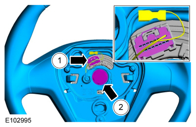
Disconnect the steering wheel electrical connector.
-
Remove the steering wheel bolt and the steering wheel.
Torque: 30 lb.ft (40 Nm)
-
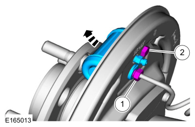
Disconnect the steering wheel electrical connector.
 |
-
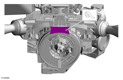
NOTICE: Make sure that the clockspring rotor does not rotate.
Tape the clockspring rotor to the outer housing to keep it from rotating.
Use the General Equipment: Adhesive Tape
 |
Installation
-
To install, reverse the removal procedure.
 Steering Column Shaft. Removal and Installation
Special Tool(s) /
General Equipment
Steering Wheel Holder
Removal
NOTE:
The removal steps in this procedure may include installation details...

Other information:
Ford Fiesta 2014 - 2019 Service Manual: Evaporative Emission Canister Ventilation Filter. Removal and Installation
Removal NOTE: Removal steps in this procedure may contain installation details. Remove the EVAP canister. Refer to: Evaporative Emission Canister (303-13B Evaporative Emissions - 1.6L EcoBoost (132kW/180PS) – Sigma, Removal and Installation). Remove the EVAP canister solenoid. Release the tabs and re..
Ford Fiesta 2014 - 2019 Service Manual: Pinpoint Test - DTC: Q. Diagnosis and Testing
B1405:11, B1405:12, B1405:13 and B1405:1A Refer to Wiring Diagrams Cell 46 for schematic and connector information. Normal Operation and Fault Conditions The RCM continuously monitors the LH side air curtain circuits for the following faults: Resistance out of range Unexpected voltage Short to ground Faulted LH side air curtain ..
Categories
- Manuals Home
- Ford Fiesta Service Manual (2014 - 2019)
- Engine - 1.6L EcoBoost (132kW/180PS) – Sigma
- Timing Belt. Removal and Installation
- Climate Control System - General Information
- Engine Cooling - 1.6L EcoBoost (132kW/180PS) – Sigma
- Valve Clearance Adjustment. General Procedures
Brake Backing Plate. Removal and Installation
Removal
NOTE: Removal steps in this procedure may contain installation details.
Remove the brake shoes.Refer to: Brake Shoes (206-02 Drum Brake, Removal and Installation).
Disconnect the brake tube fitting.
Torque: 159 lb.in (18 Nm) Remove the bolt and wheel cylinder.
Torque: 106 lb.in (12 Nm)
 Disconnect the brake shoe lever fitting and re
Copyright © 2025 www.fofiesta7.com