Ford Fiesta: Rear End Sheet Metal Repairs / Rear Side Member Section - 5-Door. Removal and Installation
Ford Fiesta 2014 - 2019 Service Manual / Body and Paint / Rear End Sheet Metal Repairs / Rear Side Member Section - 5-Door. Removal and Installation
Special Tool(s) / General Equipment
| Resistance Spotwelding Equipment | |
| 8 mm Drill Bit | |
| MIG/MAG Welding Equipment | |
| Spot Weld Drill Bit |
Materials
| Name | Specification |
|---|---|
| Seam Sealer TA-2-B, 3M™ 08308, LORD Fusor® 803DTM |
- |
Removal
-
If required , dimensionally restore the vehicle to pre-accident condition.
Refer to: Body and Frame (501-26 Body Repairs - Vehicle Specific Information and Tolerance Checks, Description and Operation).
-
Remove the following items.
Refer to: Wheel and Tire (204-04A Wheels and Tires, Removal and Installation).
Refer to: Rear Bumper (501-19 Bumpers, Removal and Installation).
-
Remove the rear wheel splash shield.
-
Drill out the spot welds.
Use the General Equipment: Spot Weld Drill Bit
 |
-
Drill out the spot welds.
Use the General Equipment: Spot Weld Drill Bit
 |
-
Drill out the spot welds and remove the rear side member section.
Use the General Equipment: Spot Weld Drill Bit
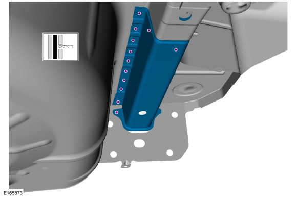 |
Installation
-
Drill holes in the replacement panel for plug welding.
Use the General Equipment: 8 mm Drill Bit
 |
-
Install the rear side member section and welds.
Use the General Equipment: MIG/MAG Welding Equipment
Use the General Equipment: Resistance Spotwelding Equipment
 |
-
Install the welds.
Use the General Equipment: MIG/MAG Welding Equipment
Use the General Equipment: Resistance Spotwelding Equipment
 |
-
Install the spot welds.
Use the General Equipment: Resistance Spotwelding Equipment
 |
-
Metal finish the repair area using typical metal finishing techniques.
-
Seam Sealing: All seams must be sealed to production level.
Material: Seam Sealer / TA-2-B, 3M™ 08308, LORD Fusor® 803DTM
 |
-
Refinish using a Ford approved paint system.
-
Restore corrosion protection.
Refer to: Corrosion Prevention (501-25 Body Repairs - General Information, General Procedures).
-
Install the rear wheel splash shield.
-
Install the following items.
Refer to: Wheel and Tire (204-04A Wheels and Tires, Removal and Installation).
Refer to: Rear Bumper (501-19 Bumpers, Removal and Installation).
Refer to: Rear Bumper Cover (501-19 Bumpers, Disassembly and Assembly).


Other information:
Ford Fiesta 2014 - 2019 Service Manual: Steering Wheel and Column Electrical Components - System Operation and Component Description. Description and Operation
System Operation System Diagram - Conventional Ignition Switch Item Description 1 START 2 ACC or ON 3 ON or START 4 IPC 5 Floor Shifter 6 Ignition Switch 7 Ignition Key Inhibit Solenoid 8 PCM 9 BCM 10 CJB 11 Ignition Relay 12 Fuses ..
Ford Fiesta 2014 - 2019 Service Manual: Steering Wheel and Column Electrical Components. Diagnosis and Testing
DTC Charts BCM DTC Chart Diagnostics in this manual assume a certain skill level and knowledge of Ford-specific diagnostic practices. REFER to: Diagnostic Methods (100-00 General Information, Description and Operation). DTC Description Action B1142:13 Ignition Status 1: Circuit Open ..
Categories
- Manuals Home
- Ford Fiesta Service Manual (2014 - 2019)
- Timing Belt. Removal and Installation
- Manual Transmission - 6-Speed Manual Transmission – B6
- Engine Cooling - 1.6L EcoBoost (132kW/180PS) – Sigma
- Manual Transmission, Clutch, Transfer Case and Power Transfer Unit
- Transmission Fluid Level Check. General Procedures
Wheels and Tires. Diagnosis and Testing
Preliminary Inspection
Verify the customer concern by carrying out a road test on a smooth road. If any vibrations are apparent, Refer to the Symptom Chart: NVH.To maximize tire performance, inspect for signs of incorrect inflation and uneven wear, which may indicate a need for balancing, rotation or front suspension alignment.
Correct tire pressure and driving techniques have an important influence on tire life. Heavy cornering, excessively rapid acceleration and unnecessary sharp braking increase tire wear.
Correct tire pressure and driving techniques have an important influence on tire life. Heavy cornering, exce
Copyright © 2024 www.fofiesta7.com