Ford Fiesta: Exterior Lighting / Rear Lamp Assembly. Removal and Installation
Ford Fiesta 2014 - 2019 Service Manual / Lighting / Exterior Lighting / Rear Lamp Assembly. Removal and Installation
Removal
4-Door sedan rear outer lamp assembly
NOTE: LH shown, RH similar.
-
-
Remove the push pin retainer.
-
Position aside the RH or LH luggage compartment side trim panel.
-
Remove the push pin retainer.
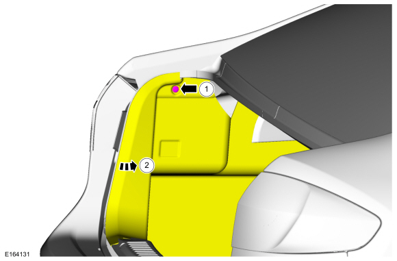 |
-
-
Disconnect the rear lamp assembly electrical connector.
-
Remove the retainer.
-
Remove the rear lamp assembly.
-
Disconnect the rear lamp assembly electrical connector.
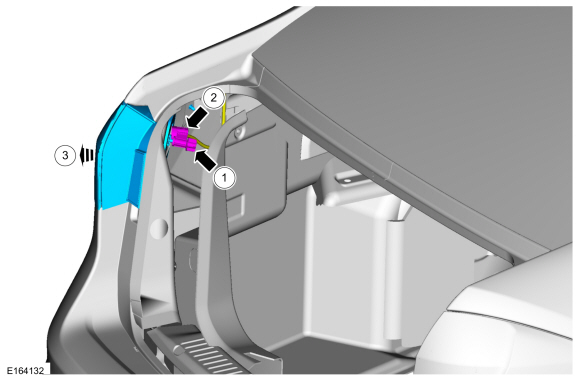 |
4-Door sedan rear inner lamp assembly
-
Remove the push pin retainers and remove the liftgate trim panel.
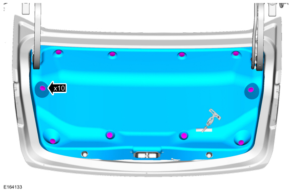 |
-
NOTE: RH shown, LH similar.
-
Disconnect the electrical connector.
-
Remove the nuts.
-
Slide the inner lamp assembly.
-
Remove inner rear lamp assembly.
-
Disconnect the electrical connector.
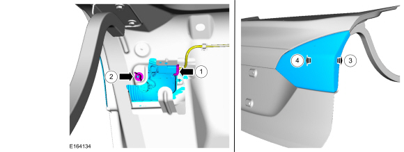 |
5-door
-
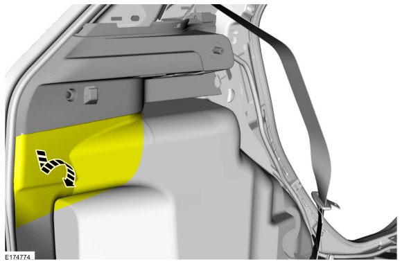
Position the luggage compartment side trim panel aside.
 |
-
NOTE: LH shown, RH similar.
-
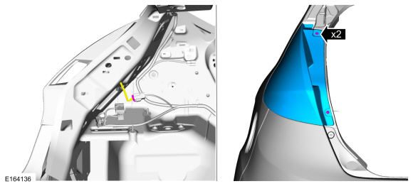
Disconnect the electrical connector.
-
Remove the screws.
-
Remove the rear lamp assembly.
-
Disconnect the electrical connector.
 |
Installation
-
To install, reverse the removal procedure.
 High Mounted Stoplamp. Removal and Installation
Removal
4-door
Remove the high mounted stop lamp cover.
Disconnect the high mounted stoplamp electrical connector...
 Front Fog Lamp Bulb. Removal and Installation
Removal
Remove the appropriate wheel and tire.
Refer to: Wheel and Tire (204-04A Wheels and Tires, Removal and Installation).
NOTE:
If equipped with air dam extensions...
Other information:
Ford Fiesta 2014 - 2019 Service Manual: Exterior Front Door Handle Reinforcement. Removal and Installation
Removal NOTE: LH side shown, RH side similar. Remove the front door latch. Refer to: Front Door Latch (501-14 Handles, Locks, Latches and Entry Systems, Removal and Installation). NOTE: This step is only necessary when installing a new component...
Ford Fiesta 2014 - 2019 Service Manual: Power Door Window Initialization. General Procedures
Initialization WARNING: Before beginning any service procedure in this section, refer to Safety Warnings in section 100-00 General Information. Failure to follow this instruction may result in serious personal injury. Refer to: Health and Safety Precautions (100-00 General Information, Description and Operation)...
Categories
- Manuals Home
- Ford Fiesta Service Manual (2014 - 2019)
- Camshafts. Removal and Installation
- Engine - 1.6L EcoBoost (132kW/180PS) – Sigma
- Timing Belt. Removal and Installation
- Maintenance Schedules
- Engine Component View. Description and Operation
Brake Backing Plate. Removal and Installation
Removal
NOTE: Removal steps in this procedure may contain installation details.
Remove the brake shoes.Refer to: Brake Shoes (206-02 Drum Brake, Removal and Installation).
Disconnect the brake tube fitting.
Torque: 159 lb.in (18 Nm) Remove the bolt and wheel cylinder.
Torque: 106 lb.in (12 Nm)
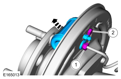 Disconnect the brake shoe lever fitting and re
Copyright © 2025 www.fofiesta7.com
