Ford Fiesta: Supplemental Restraint System / Driver Airbag. Removal and Installation
Removal
 WARNING:
The following procedure prescribes critical repair steps
required for correct restraint system operation during a crash. Follow
all notes and steps carefully. Failure to follow step instructions may
result in incorrect operation of the restraint system and increases the
risk of serious personal injury or death in a crash.
WARNING:
The following procedure prescribes critical repair steps
required for correct restraint system operation during a crash. Follow
all notes and steps carefully. Failure to follow step instructions may
result in incorrect operation of the restraint system and increases the
risk of serious personal injury or death in a crash.
-
Depower the SRS .
Refer to: Supplemental Restraint System (SRS) Depowering and Repowering (501-20B Supplemental Restraint System, General Procedures).
-
-
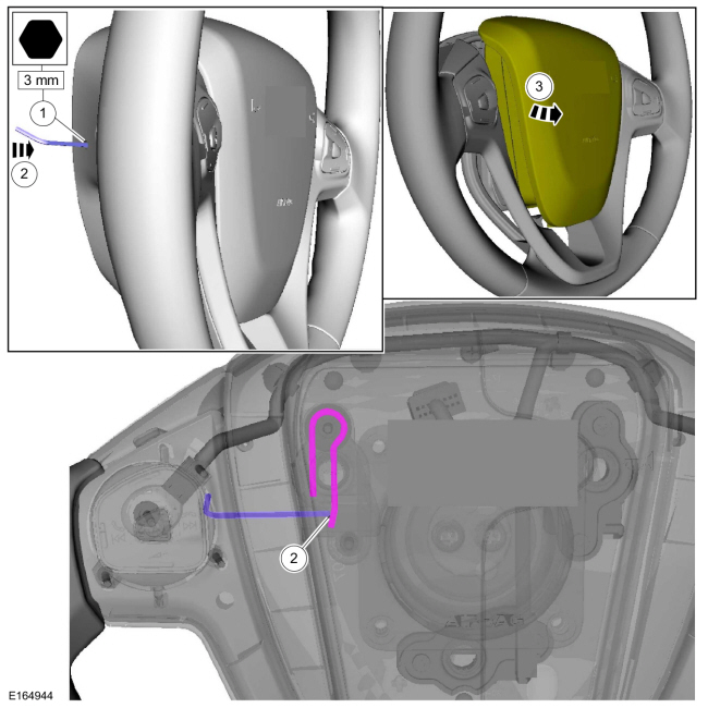
At the side of the steering wheel cover, locate the hole and insert a 3 mm (0.125 inch) Allen key.
-
Align the Allen key to contact the spring clip, push
in and disengage the spring clip from the driver airbag retainer.
-
Pull the driver airbag out and separate it from the steering wheel.
-
At the side of the steering wheel cover, locate the hole and insert a 3 mm (0.125 inch) Allen key.
 |
-
-
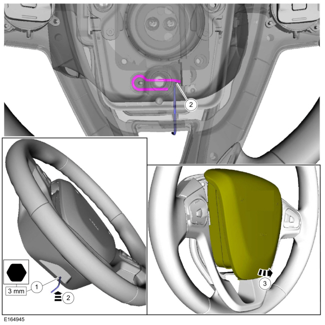
At the bottom of the steering wheel cover, locate the hole and insert a 3 mm (0.125 inch) Allen key.
-
Align the Allen key to contact the spring clip, push
in and disengage the spring clip from the driver airbag retainer.
-
Pull the driver airbag out and separate it from the steering wheel.
-
At the bottom of the steering wheel cover, locate the hole and insert a 3 mm (0.125 inch) Allen key.
 |
-
-
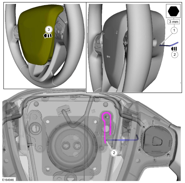
At the side of the steering wheel cover, locate the hole and insert a 3 mm (0.125 inch) Allen key.
-
Align the Allen key to contact the spring clip, push
in and disengage the spring clip from the driver airbag retainer.
-
Pull the driver airbag out and separate it from the steering wheel.
-
At the side of the steering wheel cover, locate the hole and insert a 3 mm (0.125 inch) Allen key.
 |
-
Disconnect the electrical connectors and remove the driver airbag.
 |
Installation
WARNING:
Incorrect repair techniques or actions can cause an
accidental pyrotechnic device deployment. Make sure the supplemental
restraint and pedestrian protection system (if equipped) is depowered
before reconnecting the component. Refer to the depowering General
Procedure in section 501-20B. Failure to precisely follow depowering
instructions could result in serious personal injury from an accidental
deployment.
-
Connect the electrical connectors.
|
-
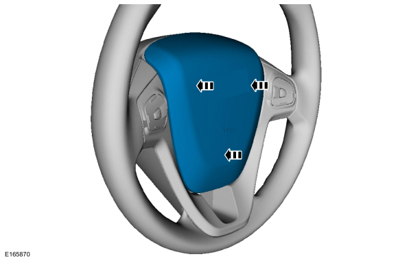
Align the driver airbag to the steering wheel and push
in, engaging the driver airbag retainers to the spring clips.
 |
-
Repower the SRS .
Refer to: Supplemental Restraint System (SRS) Depowering and Repowering (501-20B Supplemental Restraint System, General Procedures).
 C-Pillar Side Impact Sensor. Removal and Installation
Removal
WARNING:
The following procedure prescribes critical repair steps
required for correct restraint system operation during a crash...
 Front Door Side Impact Sensor. Removal and Installation
Removal
WARNING:
The following procedure prescribes critical repair steps
required for correct restraint system operation during a crash...
Other information:
Ford Fiesta 2014 - 2019 Service Manual: Crankshaft Rear Seal. Removal and Installation
Removal Remove the following items: Remove the flywheel. Refer to: Flywheel (303-01A Engine - 1.6L Duratec-16V Ti-VCT (88kW/120PS) – Sigma, Removal and Installation). Remove the oil pan. Refer to: Oil Pan (303-01A Engine - 1...
Ford Fiesta 2014 - 2019 Service Manual: Instrument Panel Cluster (IPC) - Overview. Description and Operation
Overview Item Description 1 Left turn signal indicator 2 Door ajar indicator 3 Grade assist indicator 4 TPMS warning indicator 5 Tachometer 6 Powertrain malfunction (wrench)/service warning indicator 7 ABS warning indicator 8 Integrated LCD 9 Charging system warning indicato..
Categories
- Manuals Home
- Ford Fiesta Service Manual (2014 - 2019)
- Jacking and Lifting - Overview. Description and Operation
- Engine. Assembly
- Engine
- Engine Cooling - 1.6L EcoBoost (132kW/180PS) – Sigma
- Engine Component View. Description and Operation
Brake Drum. Removal and Installation
Removal
NOTE: Removal steps in this procedure may contain installation details.
 WARNING:
Before beginning any service procedure in this
manual, refer to health and safety warnings in section 100-00 General
Information. Failure to follow this instruction may result in serious
personal injury.
WARNING:
Before beginning any service procedure in this
manual, refer to health and safety warnings in section 100-00 General
Information. Failure to follow this instruction may result in serious
personal injury.
Remove the wheel and tire.
Refer to: Wheel and Tire (204-04A Wheels and Tires, Removal and Installation).