Ford Fiesta: Supplemental Restraint System / C-Pillar Side Impact Sensor. Removal and Installation
Removal
 WARNING:
The following procedure prescribes critical repair steps
required for correct restraint system operation during a crash. Follow
all notes and steps carefully. Failure to follow step instructions may
result in incorrect operation of the restraint system and increases the
risk of serious personal injury or death in a crash.
WARNING:
The following procedure prescribes critical repair steps
required for correct restraint system operation during a crash. Follow
all notes and steps carefully. Failure to follow step instructions may
result in incorrect operation of the restraint system and increases the
risk of serious personal injury or death in a crash.
NOTE: RH side shown, LH side similar.
NOTE: To avoid damage to the trim panels, remove any retaining clips from the body and attach them to the trim panels before installing.
NOTE: Removal steps in this procedure may contain installation details.
All vehicles
-
Depower the SRS .
Refer to: Supplemental Restraint System (SRS) Depowering and Repowering (501-20B Supplemental Restraint System, General Procedures).
-
Position aside the rear door weatherstrip.
 |
4-Door
-
NOTE: Rear seat and safety belt removed for clarity.
Release the clips and position aside the C-pillar upper trim panel.
 |
All vehicles
-
NOTE: 4-door shown, 5-door similar.
Release the clips and position aside the C-pillar lower trim panel.
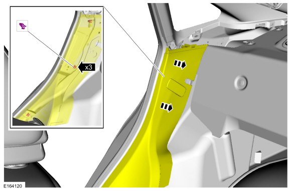 |
-
Remove the bolt, disconnect the electrical connector and remove the side impact sensor.
Torque: 93 lb.in (10.5 Nm)
 |
Installation
-
NOTE: Make sure the C-pillar and side impact sensor mating surfaces are clean and free of foreign material.
To install, reverse the removal procedure.
-
Repower the SRS .
Refer to: Supplemental Restraint System (SRS) Depowering and Repowering (501-20B Supplemental Restraint System, General Procedures).
 Clockspring. Removal and Installation
Removal
WARNING:
The following procedure prescribes critical repair steps
required for correct restraint system operation during a crash...
 Driver Airbag. Removal and Installation
Removal
WARNING:
The following procedure prescribes critical repair steps
required for correct restraint system operation during a crash...
Other information:
Ford Fiesta 2014 - 2019 Service Manual: Pinpoint Test - DTC: D. Diagnosis and Testing
B0010:11, B0010:12, B0010:13 and B0010:1A Refer to Wiring Diagrams Cell 46 for schematic and connector information. Normal Operation and Fault Conditions The RCM continuously monitors the passenger airbag stage 1 circuits for the following faults: Resistance out of range Unexpected voltage Short to ground Faulted passenger airbag ..
Ford Fiesta 2014 - 2019 Service Manual: Manual Transmission - Overview. Description and Operation
The B6 6-speed manual transmission is a fully synchronized transmission including reverse gear. The 1st and 2nd gears are triple cone synchronized. The 3rd, 4th, 5th, 6th and reverse gears are single cone synchronized. The function of the transmission is to move the vehicle from a rest position to motion. This is done by transferring the engine torque, through the transmission, to the fr..
Categories
- Manuals Home
- Ford Fiesta Service Manual (2014 - 2019)
- Engine
- Maintenance Schedules
- Clutch - 6-Speed Manual Transmission – B6
- Engine - 1.6L EcoBoost (132kW/180PS) – Sigma
- Service Information
Rear Wheel Speed Sensor. Removal and Installation
Removal
NOTE: Removal steps in this procedure may contain installation details.
Remove the retainer and pull the rear splash shield outward. Disconnect the electrical connector and detach the wiring retainer.