Ford Fiesta: Engine - 1.6L EcoBoost (132kW/180PS) – Sigma / Cylinder Head. Removal and Installation
Special Tool(s) / General Equipment
| Strap Wrench | |
| Oil Drain Equipment | |
| Hose Clamp Remover/Installer |
Materials
| Name | Specification |
|---|---|
| Motorcraft® Metal Surface Prep Wipes ZC-31-B |
- |
| Engine Oil - SAE 5W-20 - Synthetic Blend Motor Oil XO-5W20-Q1SP |
WSS-M2C945-B1 |
Removal
-
Refer to: Jacking and Lifting - Overview (100-02 Jacking and Lifting, Description and Operation).
-
Refer to: Fuel System Pressure Release (310-00B Fuel System - General
Information - 1.6L EcoBoost (132kW/180PS) – Sigma, General Procedures).
-
Remove the following items:
-
Refer to: Turbocharger (303-04C Fuel Charging and Controls -
Turbocharger - 1.6L EcoBoost (132kW/180PS) – Sigma, Removal and
Installation).
-
Refer to: Camshafts (303-01A Engine - 1.6L Duratec-16V Ti-VCT (88kW/120PS) – Sigma, Removal and Installation).
-
Refer to: Intake Manifold (303-01A Engine - 1.6L Duratec-16V Ti-VCT (88kW/120PS) – Sigma, Removal and Installation).
-
Refer to: Turbocharger (303-04C Fuel Charging and Controls -
Turbocharger - 1.6L EcoBoost (132kW/180PS) – Sigma, Removal and
Installation).
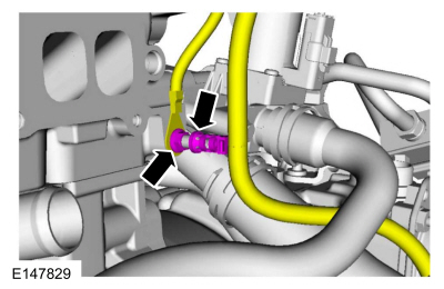 |
- Use the General Equipment: Hose Clamp Remover/Installer
 |
 |
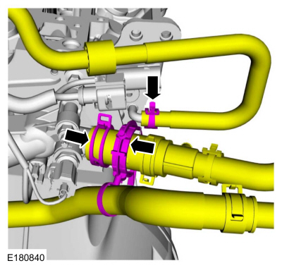
- Use the General Equipment: Hose Clamp Remover/Installer
 |
-
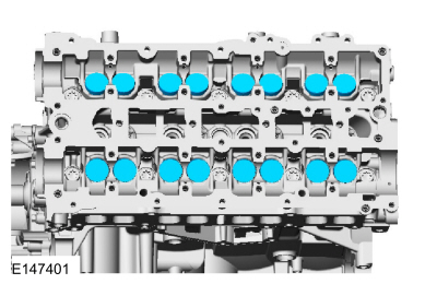
NOTE: If the camshafts and valve tappets are to be reused, mark the location of the valve tappets to make sure they are assembled in their original positions.
NOTE: The number on the valve tappets only reflects the digits that follow the decimal. For example, a tappet with the number 0.650 has the thickness of 0.1437 in ( 3.65 mm).
 |
-
Install new components as necessary.
 |
-
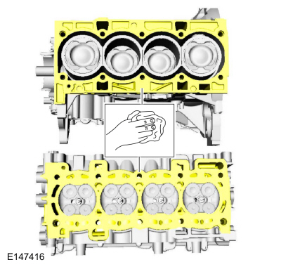
NOTE: Make sure that the cylinder head is at ambient air temperature before removing the cylinder head bolts.
 |
 |
-
Support the cylinder head on a bench with the head
gasket side up. Check the cylinder head distortion and the cylinder
block distortion.
Refer to: Cylinder Head Distortion (303-00 Engine System - General Information, General Procedures).
Refer to: Cylinder Block Distortion (303-00 Engine System - General Information, General Procedures).
Installation
-
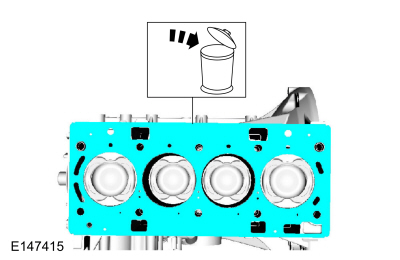
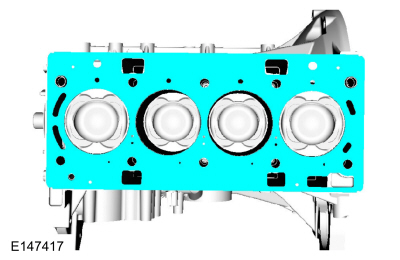
NOTICE: Do not use metal scrapers, wire brushes, power abrasive discs or other abrasive means to clean the sealing surfaces. These tools cause scratches and gouges that make leak paths. Use a plastic scraping tool to remove all traces of the head gasket.
NOTE: If there is no residual gasket material present, metal surface prep can be used to clean and prepare the surfaces.
NOTE:
Material: Motorcraft® Metal Surface Prep Wipes / ZC-31-B
 |
 |
-
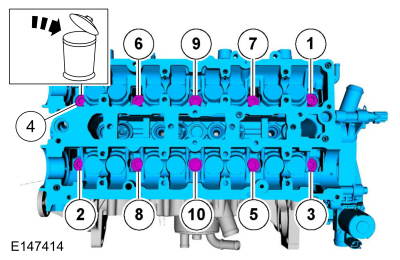
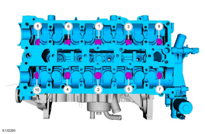
NOTE: Make sure that new bolts are installed.
NOTE: Make sure that no fluids are present in the cylinder head bolt threaded bores.
Torque:
Stage 1: 44 lb.in (5 Nm)
Stage 2: 133 lb.in (15 Nm)
Stage 3: 26 lb.ft (35 Nm)
Stage 4: 90°
Stage 5: Tighten an additional:: 90°
 |
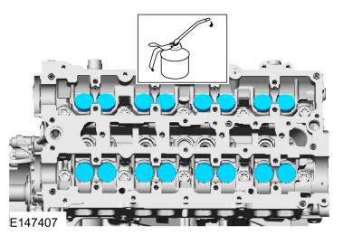
- Material: Engine Oil - SAE 5W-20 - Synthetic Blend Motor Oil / XO-5W20-Q1SP (WSS-M2C945-B1)
 |
- Use the General Equipment: Hose Clamp Remover/Installer
|
|
- Use the General Equipment: Hose Clamp Remover/Installer
|
|
-
Install the following items:
-
Refer to: Intake Manifold (303-01A Engine - 1.6L Duratec-16V Ti-VCT (88kW/120PS) – Sigma, Removal and Installation).
-
Refer to: Camshafts (303-01A Engine - 1.6L Duratec-16V Ti-VCT (88kW/120PS) – Sigma, Removal and Installation).
-
Refer to: Turbocharger (303-04C Fuel Charging and Controls -
Turbocharger - 1.6L EcoBoost (132kW/180PS) – Sigma, Removal and
Installation).
-
Refer to: Intake Manifold (303-01A Engine - 1.6L Duratec-16V Ti-VCT (88kW/120PS) – Sigma, Removal and Installation).
-
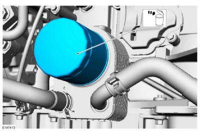
Use the General Equipment: Oil Drain Equipment
Use the General Equipment: Strap Wrench
 |
-
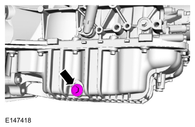
Use the General Equipment: Oil Drain Equipment
Torque: 21 lb.ft (28 Nm)
 |
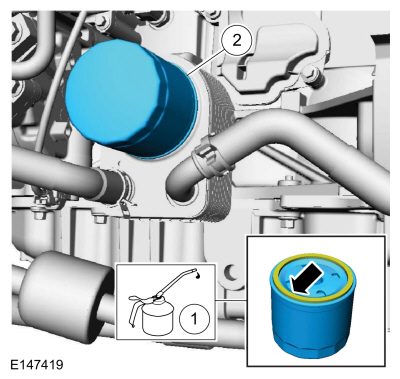
-
Material: Engine Oil - SAE 5W-20 - Synthetic Blend Motor Oil
/ XO-5W20-Q1SP
(WSS-M2C945-B1)
Torque: 128 lb.in (14.5 Nm)
 |
-
Fill the engine with clean engine oil.
Material: Engine Oil - SAE 5W-20 - Synthetic Blend Motor Oil / XO-5W20-Q1SP (WSS-M2C945-B1)

 Engine Mount. Removal and Installation
Special Tool(s) /
General Equipment
Trolley Jack
Wooden Block
Removal
Remove the degas bottle.
Refer to: Degas Bottle (303-03B Engine Cooling - 1...
Other information:
Ford Fiesta 2014 - 2019 Service Manual: Front Display Interface Module (FDIM). Removal and Installation
Removal NOTE: Removal steps in this procedure may contain installation details. Remove the instrument panel center upper trim panel. Refer to: Instrument Panel Center Upper Trim Panel (501-12 Instrument Panel and Console, Removal and Installation)...
Ford Fiesta 2014 - 2019 Service Manual: Front Seat. Removal and Installation
Removal WARNING: The following procedure describes critical repair steps required for correct seat component installation. Follow all notes and steps carefully. Do not place any objects between the seat components and the body of the vehicle, nor any objects within a joint internal to the seat structure...
Categories
- Manuals Home
- Ford Fiesta Service Manual (2014 - 2019)
- Maintenance Schedules - Gasoline Engines. Description and Operation
- Engine - 1.6L EcoBoost (132kW/180PS) – Sigma
- Engine Cooling - 1.6L EcoBoost (132kW/180PS) – Sigma
- Maintenance Schedules
- Clutch - 6-Speed Manual Transmission – B6
Brake Backing Plate. Removal and Installation
Removal
NOTE: Removal steps in this procedure may contain installation details.
Remove the brake shoes.Refer to: Brake Shoes (206-02 Drum Brake, Removal and Installation).
Disconnect the brake tube fitting.
Torque: 159 lb.in (18 Nm) Remove the bolt and wheel cylinder.
Torque: 106 lb.in (12 Nm)
 Disconnect the brake shoe lever fitting and re