Ford Fiesta: Manual Transmission - 6-Speed Manual Transmission – B6 / 3rd-4th Gear Synchronizer. Removal and Installation
Special Tool(s) /
General Equipment
 |
205-199
(T83T-3132-A1)
Installer, Spindle/Axle Shaft
T83-4000-A
TKIT-1983-F
TKIT-1983-FLM
TKIT-1983-FX |
 |
205-D015
(D80L-630-4)
Step Plate |
 |
211-014
Remover, Steering Wheel |
 |
307-003
(T57L-500-B)
Holding Fixture, Transmission |
 |
307-680
Table, Assembly (DPS6)
TKIT-2010D-FLM
TKIT-2010D-ROW |
 |
308-847
Installer, Inputshaft Seal |
 |
308-880
Installer, Driveshaft Seal |
| Hydraulic Press |
| Hot Air Gun |
| Punch |
| Adhesive Tape |
| Bearing Separator |
Materials
| Name |
Specification |
Motorcraft® Gasket Maker
TA-16 |
WSK-M2G348-A5
|
Motorcraft® Dual Clutch Transmission Fluid
XT-11-QDC |
WSS-M2C200-D2
|
Motorcraft® Silicone Brake Caliper Grease and Dielectric Compound
XG-3-A |
ESA-M1C200-A
ESE-M1C171-A
|
Removal
-
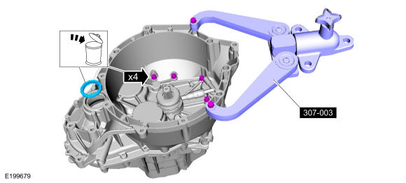
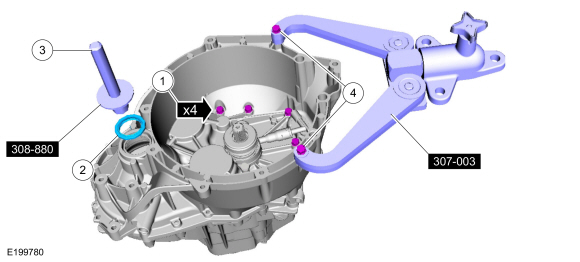
Install the special tool on the clutch housing and install the
transmission on a bench. Remove and discard the RH halfshaft and the
transmission case bolts.
Install Special Service Tool: 307-003
(T57L-500-B)
Holding Fixture, Transmission.
-
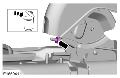
Remove the bolts and the slave cylinder.
-
NOTE:
Make sure that the selector lever is in the neutral (N) position.
Position the selector mechanism in neutral, remove the bolts and remove selector mechanism.
-
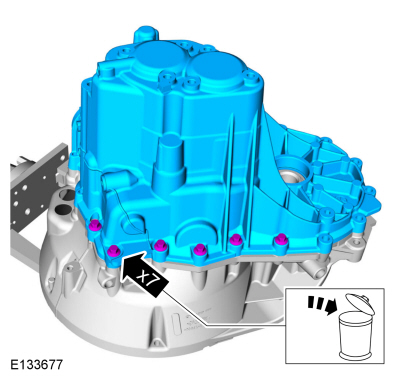
Remove the 6 rear bearing bolts.
-
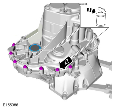
Remove and discard the transmission case bolts and the halfshaft seal.
-
Remove and discard the transmission case bolts and remove the transmission case.
-
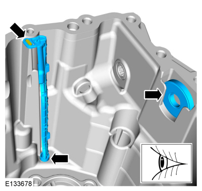
NOTE:
Note the position of the lube tube for assembly.
Remove the lube tube and the magnet from the transmission case.
-
Remove the reverse shift fork and the reverse synchronizer detents and the sleeve.
-
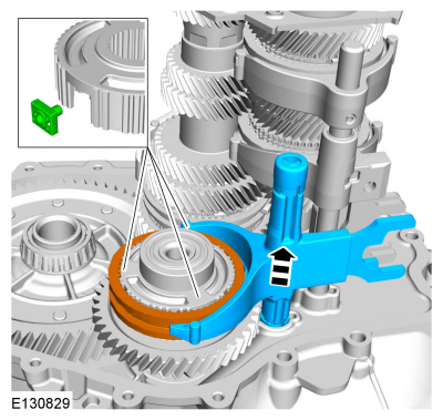
NOTE:
The differential ring gear may hang up on the shaft assemblies.
Remove the input and output shaft assemblies.
-
Remove and discard the input shaft seal.
Use the General Equipment: Punch
-
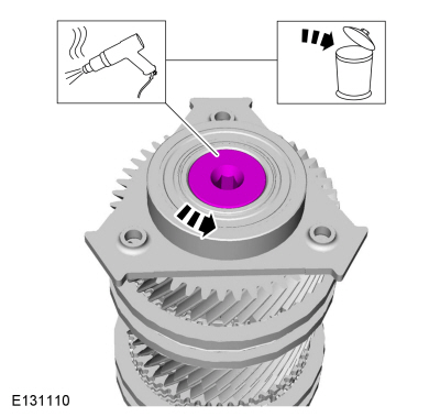
Heat the bolt to melt the Loctite® and remove and discard the rear bearing bolt.
Use the General Equipment: Hot Air Gun
-
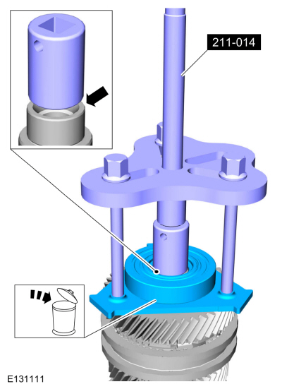
Using the special tools, remove and discard the rear bearing.
Use Special Service Tool: 211-014
Remover, Steering Wheel.
-
Remove 6th gear, 6th gear synchronizer assembly and
remove and discard the 5th-6th gear synchronizer hub snap ring.
-
Remove the 5th-6th gear synchronizer sleeve and the 3 detents.
-
Using the special tools, remove the 5th-6th gear synchronizer hub, 5th gear synchronizer assembly and 5th gear.
Use the General Equipment: Bearing Separator
Use the General Equipment: Hydraulic Press
-
NOTE:
Note the position of the components before removal.
Remove the 4th gear retainer, 4th gear and the 4th gear
synchronizer assembly. Remove and discard the 3rd-4th gear synchronizer
hub snap ring.
-
Remove the 3rd-4th gear synchronizer sleeve and the detents.
-
Using the special tools, remove the 3rd-4th gear synchronizer hub, 3rd gear synchronizer assembly, and 3rd gear.
Use the General Equipment: Bearing Separator
Use the General Equipment: Hydraulic Press
-
Remove the 3rd gear bearing.
Installation
-
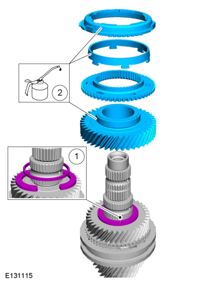
Lubricate the parts in transmission fluid and install
the 3rd gear bearing, 3rd gear and 3rd gear synchronizer assembly.
Material: Motorcraft® Dual Clutch Transmission Fluid
/ XT-11-QDC
(WSS-M2C200-D2)
-
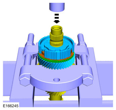
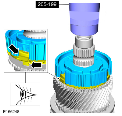
Using the special tools, install the 3rd-4th gear synchronizer hub.
Use Special Service Tool: 205-199
(T83T-3132-A1)
Installer, Spindle/Axle Shaft.
-
-
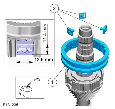
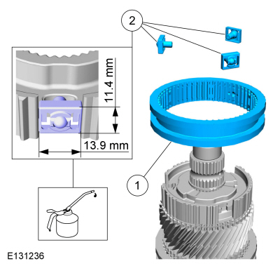
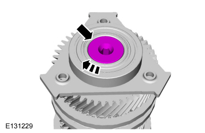
Install a new 3rd-4th gear synchronizer sleeve.
-
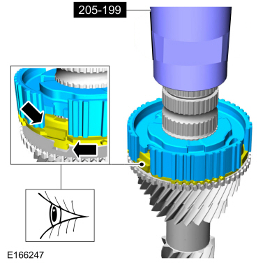
Lubricate the 3rd-4th gear synchronizer sleeve
detents in transmission fluid and install them so they fit in the
3rd-4th gear synchronizer hub as shown.
Material: Motorcraft® Dual Clutch Transmission Fluid
/ XT-11-QDC
(WSS-M2C200-D2)
-
-
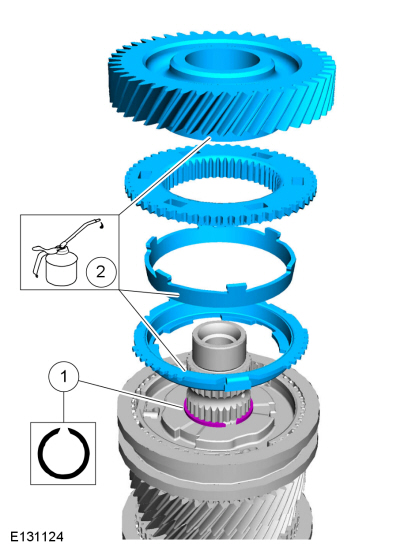
Install the 3rd-4th gear synchronizer hub snap ring.
-
Lubricate the parts in transmission fluid and
install the 4th gear synchronizer assembly and install 4th gear.
Material: Motorcraft® Dual Clutch Transmission Fluid
/ XT-11-QDC
(WSS-M2C200-D2)
-
-
NOTE:
Make sure that the components are installed to the position noted during removal.
Install the 4th gear retainer.
-
Lubricate the parts in transmission fluid and install 5th gear and the 5th gear synchronizer assembly.
Material: Motorcraft® Dual Clutch Transmission Fluid
/ XT-11-QDC
(WSS-M2C200-D2)
-
Using the special tools, install the 5th-6th gear synchronizer hub.
Use Special Service Tool: 205-199
(T83T-3132-A1)
Installer, Spindle/Axle Shaft.
Use the General Equipment: Hydraulic Press
-
-
Install the 5th-6th gear synchronizer sleeve.
-
Lubricate the 5th-6th gear synchronizer sleeve
detents in transmission fluid and install them so they fit in the
5th-6th gear synchronizer hub as shown.
Material: Motorcraft® Dual Clutch Transmission Fluid
/ XT-11-QDC
(WSS-M2C200-D2)
-
-
Install a new 5th-6th gear synchronizer hub snap ring.
-
Lubricate the parts in transmission fluid and
install the 6th gear synchronizer assembly and install 6th gear.
Material: Motorcraft® Dual Clutch Transmission Fluid
/ XT-11-QDC
(WSS-M2C200-D2)
-
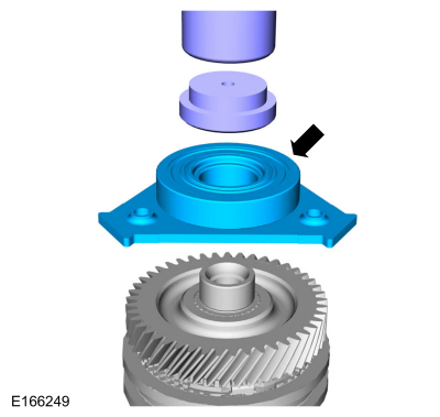
Using the special tools, install a new rear bearing.
Use Special Service Tool: 205-D015
(D80L-630-4)
Step Plate.
Use the General Equipment: Hydraulic Press
-
Install a new rear bearing bolt.
Torque:
81 lb.ft (110 Nm)
-
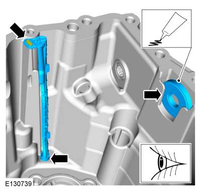
NOTE:
Install the lube tube in the same position as noted during disassembly.
Install the lube tube and the magnet in the transmission case.
Material: Motorcraft® Silicone Brake Caliper Grease and Dielectric Compound
/ XG-3-A
(ESA-M1C200-A)
(ESE-M1C171-A)
-
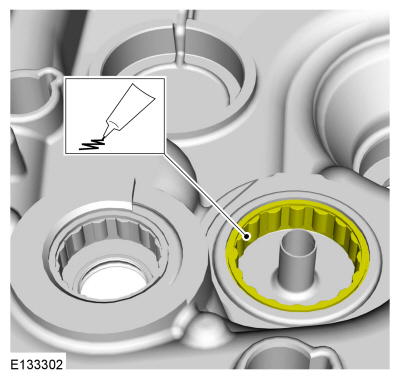
Lubricate the output shaft roller bearing.
Material: Motorcraft® Silicone Brake Caliper Grease and Dielectric Compound
/ XG-3-A
(ESA-M1C200-A)
(ESE-M1C171-A)
-
Assemble the input shaft, output shaft and the shift forks.
-
-
Lubricate the input shaft bearing and the shift rod bushing.
Material: Motorcraft® Dual Clutch Transmission Fluid
/ XT-11-QDC
(WSS-M2C200-D2)
-
NOTICE:
Be careful not to damage the bearings when installing the input shaft, output shaft and shift forks.
Position the input shaft, output shaft and shift forks into the clutch housing.
-
NOTICE:
Make sure the output shaft is aligned with the
bearing so damage does not occur to the output shaft bearing.
Align the output shaft with the output shaft roller bearing.
-
Gently lower the input shaft, output shaft and shift forks and install them in the clutch housing.
-
Lubricate the input shaft and output shaft rear bearings.
Material: Motorcraft® Dual Clutch Transmission Fluid
/ XT-11-QDC
(WSS-M2C200-D2)
 |
|
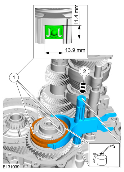
-
-
Lubricate the reverse synchronizer sleeve detents in
transmission fluid and install them so they fit in the reverse
synchronizer hub as shown.
-
Install the reverse synchronizer sleeve and reverse shift fork.
Material: Motorcraft® Dual Clutch Transmission Fluid
/ XT-11-QDC
(WSS-M2C200-D2)
-
NOTICE:
Do not use metal scrapers, wire brushes, power
abrasive discs, or other abrasive means to clean sealing surfaces. These
tools cause scratches and gouges which make leak paths.
Clean the sealing surfaces. Make sure that the mating faces are clean and free of foreign material.
-
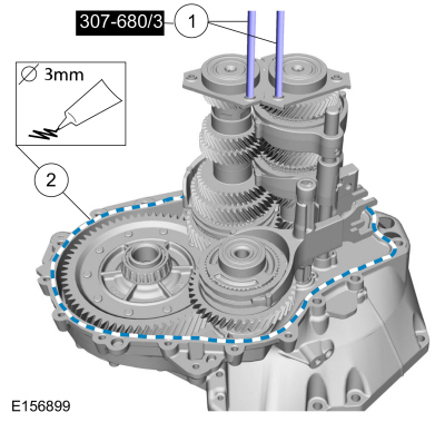
-
Install the special tools.
Install Special Service Tool: 307-680
Table, Assembly (DPS6).
-
Apply sealant to the clutch housing.
Material: Motorcraft® Gasket Maker
/ TA-16
(WSK-M2G348-A5)
-
-
NOTICE:
Make sure that new bolts are installed.
Install the transmission case and install new bolts.
Torque:
Stage 1:
159 lb.in (18 Nm)
Stage 2:
90°
-
Remove Special Service Tool: 307-680
Table, Assembly (DPS6).
-
-
NOTICE:
Make sure that new bolts are installed.
Install new transmission case bolts.
Torque:
Stage 1:
159 lb.in (18 Nm)
Stage 2:
90°
-
NOTICE:
Make sure that new bolts are installed.
Apply sealant to the underside of the bolts.
Material: Motorcraft® Gasket Maker
/ TA-16
(WSK-M2G348-A5)
-
Install new bolts.
Torque:
177 lb.in (20 Nm)
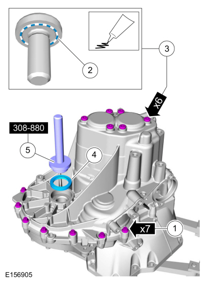
-
Position a new seal on the transmission case.
-
Using the special tool, install the seal in the transmission case.
Use Special Service Tool: 308-880
Installer, Driveshaft Seal.
-
Make sure the transmission is in neutral.
-
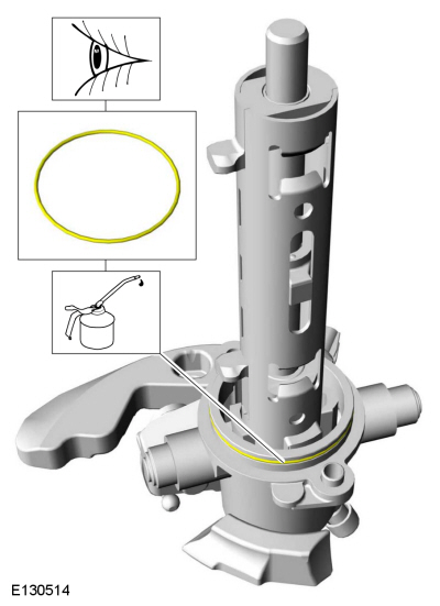
NOTE:
Re-use the O-ring seal unless it is damaged.
Lubricate and install the O-ring.
Material: Motorcraft® Dual Clutch Transmission Fluid
/ XT-11-QDC
(WSS-M2C200-D2)
-
-
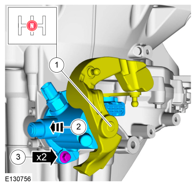
Make sure that the shift forks are in the neutral (N) position.
-
NOTICE:
Make sure that no components catch.
Install the selector mechanism.
-
Install the bolts.
Torque:
18 lb.ft (24 Nm)
-
-
NOTICE:
Use adhesive tape to cover the input shaft splines to prevent damage to the input shaft seal.
Tape the input shaft.
Use the General Equipment: Adhesive Tape
-
NOTE:
Make sure that a new component is installed.
Position a new seal on the input shaft.
-
Using the special tool, install the input shaft seal.
Use Special Service Tool: 308-847
Installer, Inputshaft Seal.
-
Remove and discard the tape.
-
Install the slave cylinder and the 2 bolts.
Torque:
89 lb.in (10 Nm)
-
-
Install new bolts.
Torque:
Stage 1:
159 lb.in (18 Nm)
Stage 2:
90°
-
Position a new LH halfshaft seal in the transmission.
-
Using the special tool, install the LH halfshaft seal.
Use Special Service Tool: 308-880
Installer, Driveshaft Seal.
-
Remove Special Service Tool: 307-003
(T57L-500-B)
Holding Fixture, Transmission.
Materials
Name
Specification
Motorcraft® Dual Clutch Transmission FluidXT-11-QDC
WSS-M2C200-D2
Draining
With the vehicle in N , position it on a hoist...
Special Tool(s) /
General Equipment
308-880Installer, Driveshaft Seal
Removal
Remove the wheel and tire.
Refer to: Wheel and Tire (204-04A Wheels and Tires, Removal and Installation)...
Other information:
Removal
NOTE:
Removal steps in this procedure may contain installation details.
With the vehicle in NEUTRAL, position it on a hoist.
Refer to: Jacking and Lifting - Overview (100-02 Jacking and Lifting, Description and Operation)...
Materials
Name
Specification
Motorcraft® Dual Clutch Transmission FluidXT-11-QDC
WSS-M2C200-D2
Check
With the vehicle in N , position it on a hoist.
Refer to: Jacking and Lifting - Overview (100-02 Jacking and Lifting, Description and Operation)...
Categories
Removal
NOTE:
Removal steps in this procedure may contain installation details.
Remove the floor console.
Refer to: Floor Console (501-12 Instrument Panel and Console, Removal and Installation).
Remove the driver seat.
Refer to: Front Seat (501-10 Seating, Removal and Installation).
Remove the parking brake cable adjustment lock nut.
Loosen the parking brake cable adjustment nut.
read more


 Transmission Draining and Filling. General Procedures
 Halfshaft Seal LH. Removal and Installation