Ford Fiesta: Supplemental Restraint System / Restraints Control Module (RCM). Removal and Installation
Removal
 WARNING:
The following procedure prescribes critical repair steps
required for correct restraint system operation during a crash. Follow
all notes and steps carefully. Failure to follow step instructions may
result in incorrect operation of the restraint system and increases the
risk of serious personal injury or death in a crash.
NOTE: Carrying out PMI will not enable the 911 assist option that is disabled. The RCM and APIM must be configured correctly to fully support 911 assist functionality.
NOTE: Removal steps in this procedure may contain installation details.
-
NOTE: This step is only necessary when installing a new component.
NOTE: The PMI process must begin with the current RCM installed. If the current RCM does not respond to the diagnostic scan tool, the tool may prompt for As-Built Data as part of the repair.
Using a diagnostic scan tool, begin the PMI process for the RCM following the on-screen instructions.
-
Depower the SRS .
Refer to: Supplemental Restraint System (SRS) Depowering and Repowering (501-20B Supplemental Restraint System, General Procedures).
-
Remove the floor console.
Refer to: Floor Console (501-12 Instrument Panel and Console, Removal and Installation).
-
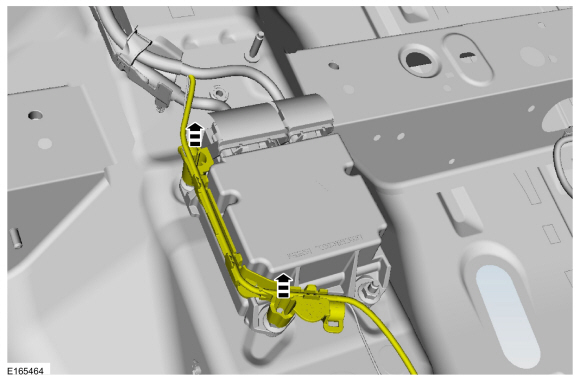
Release the wire harness retainers and position the wire harness aside.
 |
-
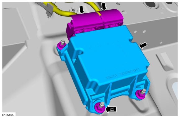
Remove the RCM .
-
Disconnect the RCM electrical connectors.
-
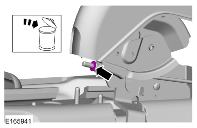
Remove the nuts.
Torque: 97 lb.in (11 Nm)
-
Remove the RCM .
-
Disconnect the RCM electrical connectors.
 |
Installation
-
To install, reverse the removal procedure.
-
Repower the SRS . Do not prove out the SRS at this time if installing a new RCM .
Refer to: Supplemental Restraint System (SRS) Depowering and Repowering (501-20B Supplemental Restraint System, General Procedures).
-
NOTE: This step is only necessary when installing a new component.
Using a diagnostic scan tool, complete the PMI process for the RCM following the on-screen instructions.
-
Prove out the SRS
by turning the ignition from ON to OFF. Wait 10 seconds, then turn the
ignition back to ON and monitor the airbag warning indicator with the
airbags installed. The airbag warning indicator illuminates continuously
for approximately 6 seconds and then turns off. If a SRS fault is
present, the airbag warning indicator will fail to light, remain lit
continuously, or flash.
-
The flashing might not occur until approximately 30
seconds after the ignition has been turned from OFF to ON. This is the
time required for the RCM to complete the testing of the SRS . If the airbag warning indicator is inoperative and a SRS
fault exists, a chime sounds in a pattern of 5 sets of 5 beeps. If
this occurs, diagnose and repair the airbag warning indicator and any SRS faults.
-
Clear all continuous Diagnostic Trouble Codes (DTCs) from the RCM and OCSM using a diagnostic scan tool.
 Passenger Airbag. Removal and Installation
Removal
WARNING:
The following procedure prescribes critical repair steps
required for correct restraint system operation during a crash...
 Seat Position Sensor. Removal and Installation
Removal
NOTE:
Removal steps in this procedure may contain installation details.
WARNING:
Turn the ignition OFF and wait one minute to deplete
the backup power supply...
Other information:
Ford Fiesta 2014 - 2019 Service Manual: Pinpoint Test - DTC: II. Diagnosis and Testing
U0100:00 Normal Operation and Fault Conditions The OCSM and RCM both use information contained in messages from the PCM sent on the HS-CAN . DTC Fault Trigger Conditions DTC Description Fault Trigger Conditions U0100:00 Lost Communication with ECM/PCM “A”: ..
Ford Fiesta 2014 - 2019 Service Manual: Evaporative Emission System Leak Test. General Procedures
Activation Disconnect the vapor tube-to-EVAP canister purge valve quick connect coupling (engine side). Refer to: Quick Release Coupling (310-00B Fuel System - General Information - 1.6L EcoBoost (132kW/180PS) – Sigma, General Procedures). Connect the VACUTEC Smoke Machine Fuel Evaporative Emission Tester to the EVAP canister purge valve fitting. Refer to the..
Categories
- Manuals Home
- Ford Fiesta Service Manual (2014 - 2019)
- Engine Cooling - 1.6L EcoBoost (132kW/180PS) – Sigma
- Front Strut and Spring Assembly. Removal and Installation
- Engine System - General Information
- Fuel Pump. Removal and Installation
- Engine - 1.6L EcoBoost (132kW/180PS) – Sigma
Parking Brake Control. Removal and Installation
Removal
NOTE: Removal steps in this procedure may contain installation details.
Remove the floor console.Refer to: Floor Console (501-12 Instrument Panel and Console, Removal and Installation).
Remove the driver seat.
Refer to: Front Seat (501-10 Seating, Removal and Installation).
Remove the parking brake cable adjustment lock nut.
 Loosen the parking brake cable adjustment nut.
