Ford Fiesta: Instrumentation, Message Center and Warning Chimes / Instrument Panel Cluster (IPC) - Overview. Description and Operation
Overview
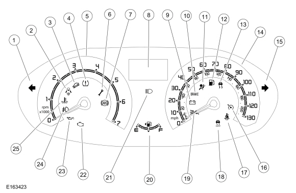
| Item | Description |
|---|---|
| 1 | Left turn signal indicator |
| 2 | Door ajar indicator |
| 3 | Grade assist indicator |
| 4 | TPMS warning indicator |
| 5 | Tachometer |
| 6 | Powertrain malfunction (wrench)/service warning indicator |
| 7 | ABS warning indicator |
| 8 | Integrated LCD |
| 9 | Charging system warning indicator |
| 10 | Brake warning indicator |
| 11 | Airbag warning indicator |
| 12 | Low fuel warning indicator |
| 13 | Stability-traction control (sliding car icon) indicator |
| 14 | Speedometer |
| 15 | Right turn signal indicator |
| 16 | Cruise control indicator |
| 17 | Safety belt warning indicator |
| 18 | Stability-traction control disabled (sliding car OFF icon) indicator |
| 19 | Lights on indicator |
| 20 | Fuel gauge |
| 21 | High beam indicator |
| 22 | MIL |
| 23 | Low oil pressure warning indicator |
| 24 | Front fog lamp indicator |
| 25 | Engine temperature warning indicator |
The IPC contains gauges, informational indicators, warning indicators and an integrated LCD designed to provide the driver with system status and to alert the driver when certain conditions exist in the vehicle.
Gauges
Gauges inform the driver of the status of systems. The systems that use gauges are as follows:
- Engine rpm
- Fuel level
- Vehicle speed
Informational and Warning Indicators
Informational indicators provide information to the driver of conditions that exist in the vehicle. Warning indicators provide information to the driver of conditions that could potentially cause personal injury or alter vehicle performance.
All informational and warning indicators are Light Emitting Diodes (LEDs) and are not replaced separate from the IPC .
IPC Integrated LCD
The IPC integrated LCD , located in the top center of the IPC , uses a 3-line LCD . The IPC integrated LCD is controlled by the trip computer switch, located on the multifunction switch. The IPC integrated LCD provides the following information:
- Odometer
-
Trip odometer
- DTE
- average fuel economy
- average speed
- instantaneous fuel economy
- outside air temperature
- Engine temperature gauge
- PRNDL (automatic transmission only)
Network Messaged Inputs
Module messaging has increased over time and has become the standard for sending and receiving information required to operate the IPC . The majority of the inputs required to operate the IPC are received over the CAN .
Hardwired Inputs
The IPC requires hardwired inputs from components that are not on the CAN . These components are required for specific IPC functions.
The hardwired inputs are provided by the following components:
- Fuel sender
- Clutch switch
- Parking brake position switch
- A/C switch (vehicles equipped with EMTC )
- Accelerator pedal
- Brake fluid level switch
- Ambient Air Temperature (AAT) sensor
- Park detect switch (part of the floor shifter assembly, vehicles equipped with automatic transmission)
- Cruise control switches
- Brake pedal switch

 Instrument Panel Cluster (IPC) - System Operation and Component Description. Description and Operation
System Operation
System Diagram - Gauges
Item
Description
1
Fuel pump assembly
2
ABS
3
HS-CAN
4
IPC
5
PCM
6
HS-CAN
Network Message Chart - Gauges
Module Network Input Messages - IPC
Broadcast M..
Other information:
Ford Fiesta 2014 - 2019 Service Manual: Battery. Diagnosis and Testing
General Equipment Diagnostic Battery Charger Battery Condition Test Battery condition is determined by measuring battery terminal voltage after a specific discharge current is applied for a specified time period. Visual Inspection and Diagnostic Pre-checks Diagnostics in this manual assume a certain skill level and knowledge of Ford-specific diagnostic practices..
Ford Fiesta 2014 - 2019 Service Manual: Body and Frame. Description and Operation
Body The body consists of the following: Four-door sedan Five-door hatchback High-Strength Low Alloy (HSLA), ultra high-strength steel (UHSS) and mild steels Roof outer panel constructed of mild steel Steel hood Steel luggage compartment lid Body side outer panels constructed of mild steel Dual-phase steel (DP) in select body struct..
Categories
- Manuals Home
- Ford Fiesta Service Manual (2014 - 2019)
- Service Information
- Maintenance Schedules
- Fuel Rail. Removal and Installation
- General Information
- Engine - 1.6L EcoBoost (132kW/180PS) – Sigma
Front Strut and Spring Assembly. Removal and Installation
Removal
NOTE: Removal steps in this procedure may contain installation details.
NOTE: This step is only necessary when installing a new component to the left-hand side.
Remove the nuts and position aside the remote brake fluid reservoir.Torque: 62 lb.in (7 Nm)
 Remove the strut and spring assembly upper mount nuts.
 Torque: 22 lb.ft (30 Nm)
