Ford Fiesta: Engine System - General Information / Cylinder Bore Taper. General Procedures
Ford Fiesta 2014 - 2019 Service Manual / Engine / Engine System - General Information / Cylinder Bore Taper. General Procedures
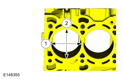
Check
NOTE: Refer to the appropriate Section 303-01 for the specification.
-
Measure the cylinder bore at the top, middle and bottom
of piston ring travel in 2 directions as indicated. Verify the cylinder
bore is within the wear limit. The difference indicates the cylinder
bore taper. If the cylinder bore taper does not meet specification, bore
the cylinder to the next oversize limit.
 |
 Cylinder Block Distortion. General Procedures
Special Tool(s) /
General Equipment
Feeler Gauge
Check
NOTE:
Refer to the appropriate Section 303-01 for the specification.
NOTE:
Use a Straightedge that is calibrated by the
manufacturer to be flat within 0...
 Cylinder Head Distortion. General Procedures
Special Tool(s) /
General Equipment
Feeler Gauge
Check
NOTE:
Refer to the appropriate Section 303-01 for the specification.
NOTE:
Make sure all cylinder head surfaces are clear of
any gasket material, silicone sealant, oil and coolant...
Other information:
Ford Fiesta 2014 - 2019 Service Manual: About this Manual. Description and Operation
Introduction WARNING: Before beginning any service procedure in this manual, refer to health and safety warnings in section 100-00 General Information. Failure to follow this instruction may result in serious personal injury. For additional information, refer to: Health and Safety Precautions (100-00 General Information, Description and Operation)...
Ford Fiesta 2014 - 2019 Service Manual: Valve Guide Inner Diameter. General Procedures
Check NOTE: Refer to the appropriate Section 303-01 for the specification. NOTE: Valve guides tend to wear in an hourglass pattern. The ball gauge can be inserted into the combustion chamber side of the valve guide, if necessary...
Categories
- Manuals Home
- Ford Fiesta Service Manual (2014 - 2019)
- Maintenance Schedules - Gasoline Engines. Description and Operation
- Engine
- General Information
- Engine - 1.6L EcoBoost (132kW/180PS) – Sigma
- Maintenance Schedules
Front Strut and Spring Assembly. Removal and Installation
Removal
NOTE: Removal steps in this procedure may contain installation details.
NOTE: This step is only necessary when installing a new component to the left-hand side.
Remove the nuts and position aside the remote brake fluid reservoir.Torque: 62 lb.in (7 Nm)
 Remove the strut and spring assembly upper mount nuts.
 Torque: 22 lb.ft (30 Nm)

Copyright © 2025 www.fofiesta7.com